การพยากรณ์อากาศด้วย Regression Analysis

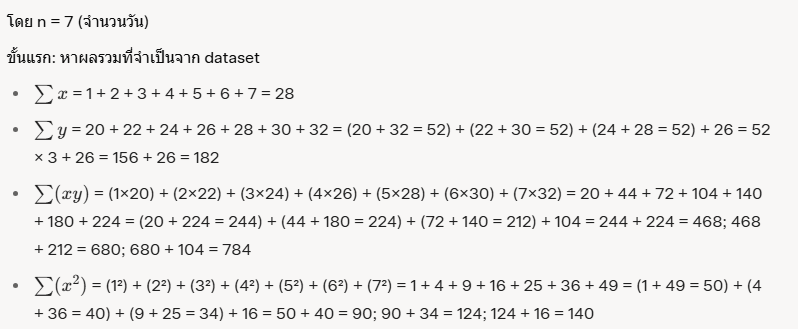
นักอุตุนิยมวิทยาที่ต้องการพยากรณ์อุณหภูมิอากาศโดยใช้เทคนิค Linear Regression Analysis (ถดถอยเชิงเส้น) จากข้อมูล time series ของอุณหภูมิเฉลี่ยรายวันในช่วง 7 วันที่ผ่านมา โดยให้วันเป็นตัวแปรอิสระ (x) และอุณหภูมิ (°C) เป็นตัวแปรตาม (y) ข้อมูล dataset มีดังนี้:

วัน (x)อุณหภูมิ (°C) (y)
120
222
324
426
528
630
732

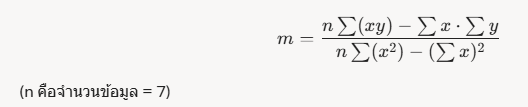
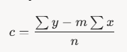
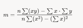
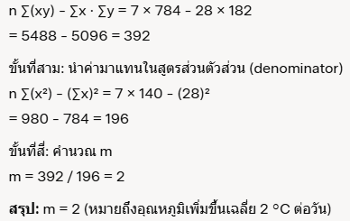
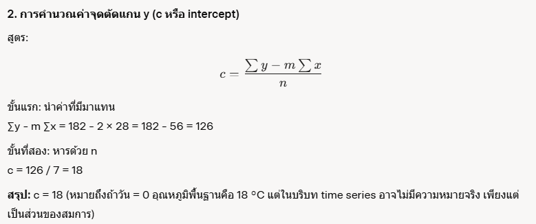
ให้คำนวณด้วยมือ (ไม่ใช้เครื่องคิดเลขหรือโปรแกรม) โดยใช้สูตร Linear Regression เพื่อหาสมการถดถอย y = mx + c จากนั้นพยากรณ์อุณหภูมิในวันที่ 8 จงตอบคำถามต่อไปนี้แบบละเอียด แสดงขั้นตอนการคำนวณทุกขั้น:

  1. คำนวณค่าความชันของเส้นถดถอย (m หรือ slope) โดยใช้สูตร

2.คำนวณค่าจุดตัดแกน y (c หรือ intercept) โดยใช้สูตร

3.เขียนสมการถดถอยเชิงเส้น (y = mx + c) ที่ได้จากการคำนวณ

4.ใช้สมการที่ได้พยากรณ์อุณหภูมิในวันที่ 8 (x = 8) และอธิบายว่าผลลัพธ์นี้บอกอะไรเกี่ยวกับแนวโน้มของอุณหภูมิ

    1. การคำนวณค่าความชัน (m หรือ slope)

    สูตร:

    ขั้นที่สอง: นำค่ามาแทนในสูตรส่วนตัวเศษ (numerator)

    3. สมการถดถอยเชิงเส้น

    จาก m = 2 และ c = 18 สมการคือ: y = 2x + 18 (โดย y คืออุณหภูมิที่พยากรณ์, x คือวัน)

    4. การพยากรณ์อุณหภูมิในวันที่ 8

    นำ x = 8 แทนในสมการ: y = 2 × 8 + 18 = 16 + 18 = 34

    การออกแบบระบบ Back-end และ Front-end Development (ESP32 web server)

     (ชุดฝึก/ชุดสาธิต/ชุดจำลอง สำหรับการเรียนการสอน)

    ——————————————–

    ชื่อนวัตกรรมการศึกษา   แบบปฏิบัติการส่งข้อมูลระหว่าง Back-end และ Front-end สำหรับฟาร์มอัจฉริยะ ประกอบการเรียนการสอนวิชา การพัฒนาแอพพลิเคชันบนอุปกรณ์เคลื่อนที่สําหรับวิศวกรรมฟาร์มอัจฉริยะ

    รหัสและชื่อรายวิชา Mobile Application Development for Smart Farm Engineering

    อธิบายวิธีการทำ ประโยชน์ พอสังเขป

    การพัฒนาแอพพลิเคชันบนอุปกรณ์เคลื่อนที่สําหรับวิศวกรรมฟาร์มอัจฉริยะ (Mobile Application Development for Smart Farm Engineering)

    รหัสวิชา 03-407-322-409

    เรื่อง การออกแบบระบบ Back-end และ Front-end Development

    1.ที่มาและความสำคัญของปัญหา

    ในยุคของเทคโนโลยีดิจิทัลและระบบอัตโนมัติ การควบคุมและตรวจสอบอุปกรณ์ไฟฟ้าหรือเซ็นเซอร์ระยะไกลผ่านเครือข่ายอินเทอร์เน็ต (IoT) กลายเป็นสิ่งสำคัญต่อการพัฒนานวัตกรรมในภาคอุตสาหกรรม การเกษตร และการดำเนินชีวิตประจำวัน หนึ่งในไมโครคอนโทรลเลอร์ที่ได้รับความนิยมคือ ESP32 ซึ่งมีคุณสมบัติในการเชื่อมต่อ Wi-Fi และ Bluetooth ได้ในตัว และสามารถประมวลผลข้อมูลร่วมกับเซ็นเซอร์หรืออุปกรณ์ควบคุมอื่นๆ ได้อย่างมีประสิทธิภาพ

    การพัฒนา Web Server บน ESP32 เป็นแนวทางที่ช่วยให้สามารถควบคุมอุปกรณ์หรือรับค่าจากเซ็นเซอร์ผ่านหน้าเว็บที่ใช้งานง่ายจากสมาร์ตโฟนหรือคอมพิวเตอร์ โดยไม่ต้องติดตั้งแอปพลิเคชันเพิ่มเติม ส่งผลให้เกิดความยืดหยุ่นสูง และสามารถปรับใช้ในระบบอัตโนมัติระดับเบื้องต้นถึงขั้นสูง เช่น สมาร์ตฟาร์ม สมาร์ตโฮม หรือการแจ้งเตือนจากระยะไกล

    แบบปฏิบัติการนี้จึงมีความสำคัญเพื่อให้นักศึกษามีความเข้าใจพื้นฐานของการสื่อสารผ่าน HTTP, การจัดการไฟล์ HTML บนไมโครคอนโทรลเลอร์ และการเชื่อมต่อกับระบบเครือข่าย โดยใช้เครื่องมือพัฒนาที่เข้าถึงง่าย เช่น Arduino IDE เพื่อเตรียมความพร้อมในการพัฒนานวัตกรรมจริงในอนาคต

    2.วัตถุประสงค์ของแบบปฏิบัติการ

    1. เพื่อให้เข้าใจหลักการทำงานของ Web Server เบื้องต้นบนไมโครคอนโทรลเลอร์ ESP32
    2. เพื่อฝึกเขียนโค้ดควบคุม ESP32 ด้วยภาษา C/C++ บน Arduino IDE
    3. เพื่อเรียนรู้การเชื่อมต่อ ESP32 เข้ากับระบบ Wi-Fi และการสร้าง Web Page
    4. เพื่อทดลองควบคุมอุปกรณ์จริง (เช่น LED) ผ่านอินเทอร์เฟซหน้าเว็บ
    5. เพื่อปูพื้นฐานในการพัฒนา IoT ที่สามารถรับส่งข้อมูลแบบเรียลไทม์ผ่านเว็บเบราว์เซอร์

    3.สิ่งที่คาดว่าจะได้รับจากแบบปฏิบัติการนี้

    1. ความเข้าใจในการใช้ ESP32 เพื่อเชื่อมต่อเครือข่าย Wi-Fi
    2. ความสามารถในการสร้าง Web Server ที่ฝังอยู่ในไมโครคอนโทรลเลอร์
    3. ทักษะการเขียนโค้ด HTML ร่วมกับภาษา C/C++
    4. ความเข้าใจในการรับ–ส่ง HTTP Request และ Response
    5. ทักษะในการควบคุมอุปกรณ์ทางกายภาพ (เช่น LED) ผ่านเว็บอินเตอร์เฟซ
    6. ความเข้าใจในการออกแบบระบบ IoT เบื้องต้น
    7. ทักษะการ Debugging ระบบฝังตัวผ่าน Serial Monitor
    8. ความพร้อมในการต่อยอดสู่โครงการ IoT จริง เช่น ระบบแจ้งเตือน, ระบบควบคุมระยะไกล, หรือสมาร์ตฟาร์ม

    4.กระบวนการ ขั้นตอนการปฏิบัติการ

    ภาพรวมของโปรเจ็กต์ (Project Overview)

    โปรเจ็กต์นี้จะสร้าง Web Server บน ESP32 ที่คุณสามารถควบคุมการเปิด–ปิดไฟ LED สองตัวผ่านเว็บเบราว์เซอร์ในเครือข่ายเดียวกัน โดยใช้ Arduino IDE ในการพัฒนา

    • ESP32 ทำหน้าที่เป็น HTTP server
    • มีปุ่มบนหน้าเว็บให้กดเพื่อสั่งเปิด/ปิด LED ที่เชื่อมกับพิน GPIO 26 และ GPIO 27
    • รองรับการเข้าใช้งานผ่านสมาร์ทโฟนหรือคอมพิวเตอร์ที่อยู่ในเครือข่ายเดียวกัน (mobile-responsive)

    อุปกรณ์ที่ต้องใช้ (Parts Required)

    • บอร์ด ESP32 Development Board (เช่น DOIT ESP32 DEVKIT V1)
    • LED ขนาด 5 มม. จำนวน 2 ดวง
    • ตัวต้านทาน 330 โอห์ม จำนวน 2 ตัว
    • บอร์ดทดลอง (Breadboard)
    • สาย Jumper สำหรับเชื่อมวงจร

    ขั้นตอนติดตั้ง ESP32 บน Arduino IDE (Installing the ESP32 Board)

    1. เปิด Arduino IDE แล้วไปที่ File Preferences
    2. ในช่อง “Additional Board Manager URLs” ให้ใส่:
    3.      https://raw.githubusercontent.com/espressif/arduino-esp32/gh-pages/package_esp32_index.json
    • เข้าไปที่ Tools Board Boards Manager ค้นหา “ESP32 by Espressif Systems” แล้วกดติดตั้ง
    • เลือกบอร์ด ESP32 ที่คุณใช้งาน (เช่น DOIT ESP32 DEVKIT V1) และพอร์ตที่เชื่อมต่อ

    การต่อวงจร (Schematic)

    • เชื่อม LED ตัวแรกที่ GPIO 26 ผ่านตัวต้านทาน 330Ω ไปยัง GND
    • เชื่อม LED ตัวที่สองที่ GPIO 27 ผ่านตัวต้านทาน 330Ω ไปยัง GND
    • ใช้บอร์ด ESP32 module และสังเกตให้แน่ใจว่าพินต่างๆ ถูกต้องตามรุ่นบอร์ดที่ใช้

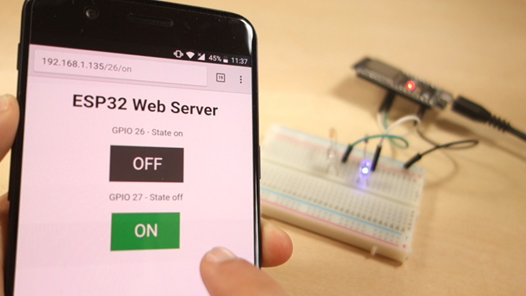
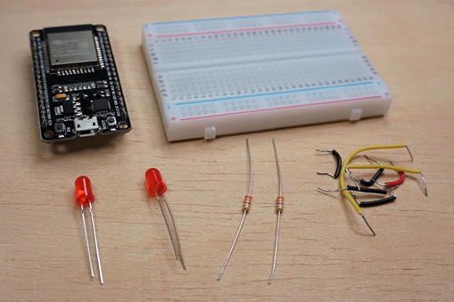
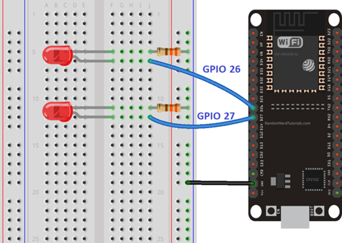
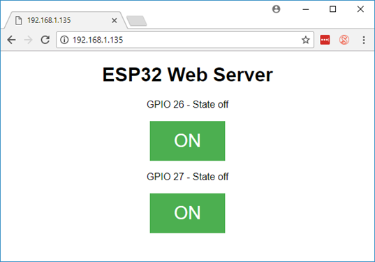
    ตัวอย่างโค้ด ESP32 Web Server (โค้ดใน Arduino IDE)

    บทความมีการแจกโค้ดแนะนำในส่วนของ “ESP32 Web Server Code” ให้ส่ง HTML หน้าเว็บเพื่อควบคุม LED และรับคำสั่งจากผู้ใช้

    โครงสร้างคร่าว ๆ ของโค้ด ได้แก่:

    /*********
      Rui Santos
      Complete project details at http://randomnerdtutorials.com  
    *********/
    
    // Load Wi-Fi library
    #include <WiFi.h>
    
    // Replace with your network credentials
    const char* ssid = "REPLACE_WITH_YOUR_SSID";
    const char* password = "REPLACE_WITH_YOUR_PASSWORD";
    
    // Set web server port number to 80
    WiFiServer server(80);
    
    // Variable to store the HTTP request
    String header;
    
    // Auxiliar variables to store the current output state
    String output26State = "off";
    String output27State = "off";
    
    // Assign output variables to GPIO pins
    const int output26 = 26;
    const int output27 = 27;
    
    // Current time
    unsigned long currentTime = millis();
    // Previous time
    unsigned long previousTime = 0; 
    // Define timeout time in milliseconds (example: 2000ms = 2s)
    const long timeoutTime = 2000;
    
    void setup() {
      Serial.begin(115200);
      // Initialize the output variables as outputs
      pinMode(output26, OUTPUT);
      pinMode(output27, OUTPUT);
      // Set outputs to LOW
      digitalWrite(output26, LOW);
      digitalWrite(output27, LOW);
    
      // Connect to Wi-Fi network with SSID and password
      Serial.print("Connecting to ");
      Serial.println(ssid);
      WiFi.begin(ssid, password);
      while (WiFi.status() != WL_CONNECTED) {
        delay(500);
        Serial.print(".");
      }
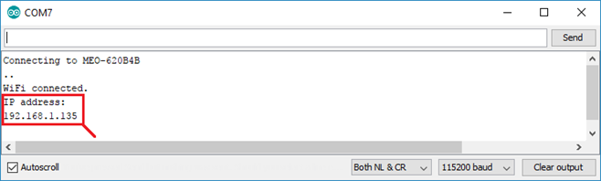
      // Print local IP address and start web server
      Serial.println("");
      Serial.println("WiFi connected.");
      Serial.println("IP address: ");
      Serial.println(WiFi.localIP());
      server.begin();
    }
    
    void loop(){
      WiFiClient client = server.available();   // Listen for incoming clients
    
      if (client) {                             // If a new client connects,
        currentTime = millis();
        previousTime = currentTime;
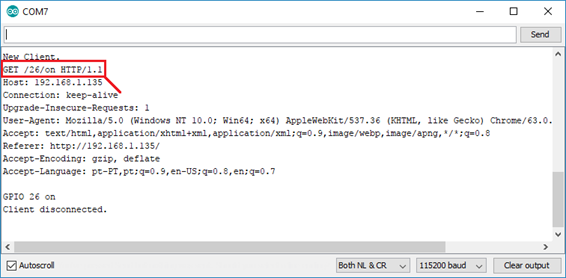
        Serial.println("New Client.");          // print a message out in the serial port
        String currentLine = "";                // make a String to hold incoming data from the client
        while (client.connected() && currentTime - previousTime <= timeoutTime) {  // loop while the client's connected
          currentTime = millis();
          if (client.available()) {             // if there's bytes to read from the client,
            char c = client.read();             // read a byte, then
            Serial.write(c);                    // print it out the serial monitor
            header += c;
            if (c == '\n') {                    // if the byte is a newline character
              // if the current line is blank, you got two newline characters in a row.
              // that's the end of the client HTTP request, so send a response:
              if (currentLine.length() == 0) {
                // HTTP headers always start with a response code (e.g. HTTP/1.1 200 OK)
                // and a content-type so the client knows what's coming, then a blank line:
                client.println("HTTP/1.1 200 OK");
                client.println("Content-type:text/html");
                client.println("Connection: close");
                client.println();
                
                // turns the GPIOs on and off
                if (header.indexOf("GET /26/on") >= 0) {
                  Serial.println("GPIO 26 on");
                  output26State = "on";
                  digitalWrite(output26, HIGH);
                } else if (header.indexOf("GET /26/off") >= 0) {
                  Serial.println("GPIO 26 off");
                  output26State = "off";
                  digitalWrite(output26, LOW);
                } else if (header.indexOf("GET /27/on") >= 0) {
                  Serial.println("GPIO 27 on");
                  output27State = "on";
                  digitalWrite(output27, HIGH);
                } else if (header.indexOf("GET /27/off") >= 0) {
                  Serial.println("GPIO 27 off");
                  output27State = "off";
                  digitalWrite(output27, LOW);
                }
                
                // Display the HTML web page
                client.println("<!DOCTYPE html><html>");
                client.println("<head><meta name=\"viewport\" content=\"width=device-width, initial-scale=1\">");
                client.println("<link rel=\"icon\" href=\"data:,\">");
                // CSS to style the on/off buttons 
                // Feel free to change the background-color and font-size attributes to fit your preferences
                client.println("<style>html { font-family: Helvetica; display: inline-block; margin: 0px auto; text-align: center;}");
                client.println(".button { background-color: #4CAF50; border: none; color: white; padding: 16px 40px;");
                client.println("text-decoration: none; font-size: 30px; margin: 2px; cursor: pointer;}");
                client.println(".button2 {background-color: #555555;}</style></head>");
                
                // Web Page Heading
                client.println("<body><h1>ESP32 Web Server</h1>");
                
                // Display current state, and ON/OFF buttons for GPIO 26  
                client.println("<p>GPIO 26 - State " + output26State + "</p>");
                // If the output26State is off, it displays the ON button       
                if (output26State=="off") {
                  client.println("<p><a href=\"/26/on\"><button class=\"button\">ON</button></a></p>");
                } else {
                  client.println("<p><a href=\"/26/off\"><button class=\"button button2\">OFF</button></a></p>");
                } 
                   
                // Display current state, and ON/OFF buttons for GPIO 27  
                client.println("<p>GPIO 27 - State " + output27State + "</p>");
                // If the output27State is off, it displays the ON button       
                if (output27State=="off") {
                  client.println("<p><a href=\"/27/on\"><button class=\"button\">ON</button></a></p>");
                } else {
                  client.println("<p><a href=\"/27/off\"><button class=\"button button2\">OFF</button></a></p>");
                }
                client.println("</body></html>");
                
                // The HTTP response ends with another blank line
                client.println();
                // Break out of the while loop
                break;
              } else { // if you got a newline, then clear currentLine
                currentLine = "";
              }
            } else if (c != '\r') {  // if you got anything else but a carriage return character,
              currentLine += c;      // add it to the end of the currentLine
            }
          }
        }
        // Clear the header variable
        header = "";
        // Close the connection
        client.stop();
        Serial.println("Client disconnected.");
        Serial.println("");
      }
    }
    

    อธิบายส่วนสำคัญ:

    • เชื่อม Wi-Fi ด้วย WiFi.begin() และรอเชื่อมต่อจนสำเร็จ
    • ใช้ server.begin() เพื่อเริ่ม HTTP server
    • ใน loop() รับการเชื่อมต่อจาก server.available() แล้วอ่าน HTTP request
    • ตรวจสอบพารามิเตอร์ (เช่น “GET /?led1=on”) เพื่อสั่งเปิด/ปิด LED
    • ส่ง HTML หน้าเว็บที่มีปุ่มกดกลับไปยังเบราว์เซอร์

    เลือก port com

    การดู IP และทดสอบ

    • เปิด Serial Monitor ที่ baud rate 115200
    • ESP32 จะแสดง IP address ที่มันได้รับ เช่น 192.168.1.123
    • เปิดเว็บเบราว์เซอร์ แล้วพิมพ์ IP นั้น ตัวอย่างเช่น http://192.168.1.123
    • หน้าเว็บจะปรากฏปุ่มควบคุม LED สองตัว เมื่อคลิกแล้ว ESP32 จะควบคุม LED ตามคำสั่งในเว็บอย่างทันที

    สรุป โปรเจ็กต์นี้ช่วยให้นักศึกษาได้เรียนรู้และเข้าใจ

    • วิธีตั้งค่า ESP32 บน Arduino IDE และต่อวงจร
    • การเชื่อม Wi‑Fi และทำ ESP32 ให้กลายเป็น Web Server พื้นฐาน
    • การรับ HTTP request, ประมวลผลคำสั่ง, และตอบกลับ HTML
    • สามารถควบคุมอุปกรณ์จริง (เช่น LED) ผ่านหน้าเว็บอินเตอร์เฟซแบบเรียลไทม์
    • ภาพรวมการออกแบบระบบ Back-end และ Front-end