(ชุดฝึก/ชุดสาธิต/ชุดจำลอง สำหรับการเรียนการสอน)
——————————————–
ชื่อนวัตกรรมการศึกษา แบบปฏิบัติการส่งข้อมูลระหว่าง Back-end และ Front-end สำหรับฟาร์มอัจฉริยะ ประกอบการเรียนการสอนวิชา การพัฒนาแอพพลิเคชันบนอุปกรณ์เคลื่อนที่สําหรับวิศวกรรมฟาร์มอัจฉริยะ
รหัสและชื่อรายวิชา Mobile Application Development for Smart Farm Engineering
อธิบายวิธีการทำ ประโยชน์ พอสังเขป
การพัฒนาแอพพลิเคชันบนอุปกรณ์เคลื่อนที่สําหรับวิศวกรรมฟาร์มอัจฉริยะ (Mobile Application Development for Smart Farm Engineering)
รหัสวิชา 03-407-322-409
เรื่อง การออกแบบระบบ Back-end และ Front-end Development
1.ที่มาและความสำคัญของปัญหา
ในยุคของเทคโนโลยีดิจิทัลและระบบอัตโนมัติ การควบคุมและตรวจสอบอุปกรณ์ไฟฟ้าหรือเซ็นเซอร์ระยะไกลผ่านเครือข่ายอินเทอร์เน็ต (IoT) กลายเป็นสิ่งสำคัญต่อการพัฒนานวัตกรรมในภาคอุตสาหกรรม การเกษตร และการดำเนินชีวิตประจำวัน หนึ่งในไมโครคอนโทรลเลอร์ที่ได้รับความนิยมคือ ESP32 ซึ่งมีคุณสมบัติในการเชื่อมต่อ Wi-Fi และ Bluetooth ได้ในตัว และสามารถประมวลผลข้อมูลร่วมกับเซ็นเซอร์หรืออุปกรณ์ควบคุมอื่นๆ ได้อย่างมีประสิทธิภาพ
การพัฒนา Web Server บน ESP32 เป็นแนวทางที่ช่วยให้สามารถควบคุมอุปกรณ์หรือรับค่าจากเซ็นเซอร์ผ่านหน้าเว็บที่ใช้งานง่ายจากสมาร์ตโฟนหรือคอมพิวเตอร์ โดยไม่ต้องติดตั้งแอปพลิเคชันเพิ่มเติม ส่งผลให้เกิดความยืดหยุ่นสูง และสามารถปรับใช้ในระบบอัตโนมัติระดับเบื้องต้นถึงขั้นสูง เช่น สมาร์ตฟาร์ม สมาร์ตโฮม หรือการแจ้งเตือนจากระยะไกล
แบบปฏิบัติการนี้จึงมีความสำคัญเพื่อให้นักศึกษามีความเข้าใจพื้นฐานของการสื่อสารผ่าน HTTP, การจัดการไฟล์ HTML บนไมโครคอนโทรลเลอร์ และการเชื่อมต่อกับระบบเครือข่าย โดยใช้เครื่องมือพัฒนาที่เข้าถึงง่าย เช่น Arduino IDE เพื่อเตรียมความพร้อมในการพัฒนานวัตกรรมจริงในอนาคต
2.วัตถุประสงค์ของแบบปฏิบัติการ
- เพื่อให้เข้าใจหลักการทำงานของ Web Server เบื้องต้นบนไมโครคอนโทรลเลอร์ ESP32
- เพื่อฝึกเขียนโค้ดควบคุม ESP32 ด้วยภาษา C/C++ บน Arduino IDE
- เพื่อเรียนรู้การเชื่อมต่อ ESP32 เข้ากับระบบ Wi-Fi และการสร้าง Web Page
- เพื่อทดลองควบคุมอุปกรณ์จริง (เช่น LED) ผ่านอินเทอร์เฟซหน้าเว็บ
- เพื่อปูพื้นฐานในการพัฒนา IoT ที่สามารถรับส่งข้อมูลแบบเรียลไทม์ผ่านเว็บเบราว์เซอร์
3.สิ่งที่คาดว่าจะได้รับจากแบบปฏิบัติการนี้
- ความเข้าใจในการใช้ ESP32 เพื่อเชื่อมต่อเครือข่าย Wi-Fi
- ความสามารถในการสร้าง Web Server ที่ฝังอยู่ในไมโครคอนโทรลเลอร์
- ทักษะการเขียนโค้ด HTML ร่วมกับภาษา C/C++
- ความเข้าใจในการรับ–ส่ง HTTP Request และ Response
- ทักษะในการควบคุมอุปกรณ์ทางกายภาพ (เช่น LED) ผ่านเว็บอินเตอร์เฟซ
- ความเข้าใจในการออกแบบระบบ IoT เบื้องต้น
- ทักษะการ Debugging ระบบฝังตัวผ่าน Serial Monitor
- ความพร้อมในการต่อยอดสู่โครงการ IoT จริง เช่น ระบบแจ้งเตือน, ระบบควบคุมระยะไกล, หรือสมาร์ตฟาร์ม
4.กระบวนการ ขั้นตอนการปฏิบัติการ
ภาพรวมของโปรเจ็กต์ (Project Overview)
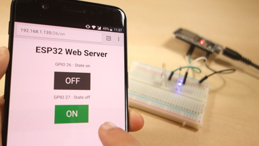
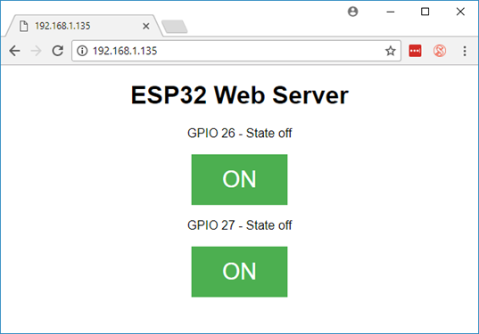
โปรเจ็กต์นี้จะสร้าง Web Server บน ESP32 ที่คุณสามารถควบคุมการเปิด–ปิดไฟ LED สองตัวผ่านเว็บเบราว์เซอร์ในเครือข่ายเดียวกัน โดยใช้ Arduino IDE ในการพัฒนา
- ESP32 ทำหน้าที่เป็น HTTP server
- มีปุ่มบนหน้าเว็บให้กดเพื่อสั่งเปิด/ปิด LED ที่เชื่อมกับพิน GPIO 26 และ GPIO 27
- รองรับการเข้าใช้งานผ่านสมาร์ทโฟนหรือคอมพิวเตอร์ที่อยู่ในเครือข่ายเดียวกัน (mobile-responsive)
อุปกรณ์ที่ต้องใช้ (Parts Required)
- บอร์ด ESP32 Development Board (เช่น DOIT ESP32 DEVKIT V1)
- LED ขนาด 5 มม. จำนวน 2 ดวง
- ตัวต้านทาน 330 โอห์ม จำนวน 2 ตัว
- บอร์ดทดลอง (Breadboard)
- สาย Jumper สำหรับเชื่อมวงจร

ขั้นตอนติดตั้ง ESP32 บน Arduino IDE (Installing the ESP32 Board)
- เปิด Arduino IDE แล้วไปที่ File → Preferences
- ในช่อง “Additional Board Manager URLs” ให้ใส่:
3. https://raw.githubusercontent.com/espressif/arduino-esp32/gh-pages/package_esp32_index.json
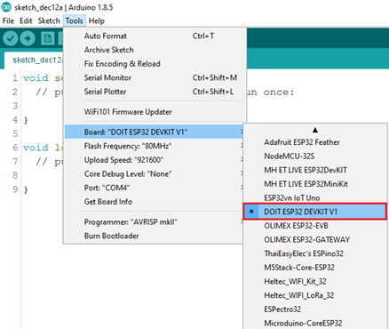
- เข้าไปที่ Tools → Board → Boards Manager ค้นหา “ESP32 by Espressif Systems” แล้วกดติดตั้ง
- เลือกบอร์ด ESP32 ที่คุณใช้งาน (เช่น DOIT ESP32 DEVKIT V1) และพอร์ตที่เชื่อมต่อ
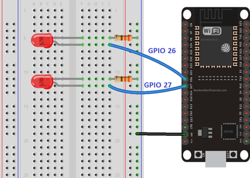
การต่อวงจร (Schematic)
- เชื่อม LED ตัวแรกที่ GPIO 26 ผ่านตัวต้านทาน 330Ω ไปยัง GND
- เชื่อม LED ตัวที่สองที่ GPIO 27 ผ่านตัวต้านทาน 330Ω ไปยัง GND
- ใช้บอร์ด ESP32 module และสังเกตให้แน่ใจว่าพินต่างๆ ถูกต้องตามรุ่นบอร์ดที่ใช้
ตัวอย่างโค้ด ESP32 Web Server (โค้ดใน Arduino IDE)
บทความมีการแจกโค้ดแนะนำในส่วนของ “ESP32 Web Server Code” ให้ส่ง HTML หน้าเว็บเพื่อควบคุม LED และรับคำสั่งจากผู้ใช้
โครงสร้างคร่าว ๆ ของโค้ด ได้แก่:
/*********
Rui Santos
Complete project details at http://randomnerdtutorials.com
*********/
// Load Wi-Fi library
#include <WiFi.h>
// Replace with your network credentials
const char* ssid = "REPLACE_WITH_YOUR_SSID";
const char* password = "REPLACE_WITH_YOUR_PASSWORD";
// Set web server port number to 80
WiFiServer server(80);
// Variable to store the HTTP request
String header;
// Auxiliar variables to store the current output state
String output26State = "off";
String output27State = "off";
// Assign output variables to GPIO pins
const int output26 = 26;
const int output27 = 27;
// Current time
unsigned long currentTime = millis();
// Previous time
unsigned long previousTime = 0;
// Define timeout time in milliseconds (example: 2000ms = 2s)
const long timeoutTime = 2000;
void setup() {
Serial.begin(115200);
// Initialize the output variables as outputs
pinMode(output26, OUTPUT);
pinMode(output27, OUTPUT);
// Set outputs to LOW
digitalWrite(output26, LOW);
digitalWrite(output27, LOW);
// Connect to Wi-Fi network with SSID and password
Serial.print("Connecting to ");
Serial.println(ssid);
WiFi.begin(ssid, password);
while (WiFi.status() != WL_CONNECTED) {
delay(500);
Serial.print(".");
}
// Print local IP address and start web server
Serial.println("");
Serial.println("WiFi connected.");
Serial.println("IP address: ");
Serial.println(WiFi.localIP());
server.begin();
}
void loop(){
WiFiClient client = server.available(); // Listen for incoming clients
if (client) { // If a new client connects,
currentTime = millis();
previousTime = currentTime;
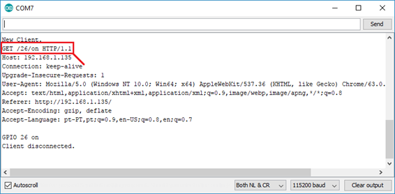
Serial.println("New Client."); // print a message out in the serial port
String currentLine = ""; // make a String to hold incoming data from the client
while (client.connected() && currentTime - previousTime <= timeoutTime) { // loop while the client's connected
currentTime = millis();
if (client.available()) { // if there's bytes to read from the client,
char c = client.read(); // read a byte, then
Serial.write(c); // print it out the serial monitor
header += c;
if (c == '\n') { // if the byte is a newline character
// if the current line is blank, you got two newline characters in a row.
// that's the end of the client HTTP request, so send a response:
if (currentLine.length() == 0) {
// HTTP headers always start with a response code (e.g. HTTP/1.1 200 OK)
// and a content-type so the client knows what's coming, then a blank line:
client.println("HTTP/1.1 200 OK");
client.println("Content-type:text/html");
client.println("Connection: close");
client.println();
// turns the GPIOs on and off
if (header.indexOf("GET /26/on") >= 0) {
Serial.println("GPIO 26 on");
output26State = "on";
digitalWrite(output26, HIGH);
} else if (header.indexOf("GET /26/off") >= 0) {
Serial.println("GPIO 26 off");
output26State = "off";
digitalWrite(output26, LOW);
} else if (header.indexOf("GET /27/on") >= 0) {
Serial.println("GPIO 27 on");
output27State = "on";
digitalWrite(output27, HIGH);
} else if (header.indexOf("GET /27/off") >= 0) {
Serial.println("GPIO 27 off");
output27State = "off";
digitalWrite(output27, LOW);
}
// Display the HTML web page
client.println("<!DOCTYPE html><html>");
client.println("<head><meta name=\"viewport\" content=\"width=device-width, initial-scale=1\">");
client.println("<link rel=\"icon\" href=\"data:,\">");
// CSS to style the on/off buttons
// Feel free to change the background-color and font-size attributes to fit your preferences
client.println("<style>html { font-family: Helvetica; display: inline-block; margin: 0px auto; text-align: center;}");
client.println(".button { background-color: #4CAF50; border: none; color: white; padding: 16px 40px;");
client.println("text-decoration: none; font-size: 30px; margin: 2px; cursor: pointer;}");
client.println(".button2 {background-color: #555555;}</style></head>");
// Web Page Heading
client.println("<body><h1>ESP32 Web Server</h1>");
// Display current state, and ON/OFF buttons for GPIO 26
client.println("<p>GPIO 26 - State " + output26State + "</p>");
// If the output26State is off, it displays the ON button
if (output26State=="off") {
client.println("<p><a href=\"/26/on\"><button class=\"button\">ON</button></a></p>");
} else {
client.println("<p><a href=\"/26/off\"><button class=\"button button2\">OFF</button></a></p>");
}
// Display current state, and ON/OFF buttons for GPIO 27
client.println("<p>GPIO 27 - State " + output27State + "</p>");
// If the output27State is off, it displays the ON button
if (output27State=="off") {
client.println("<p><a href=\"/27/on\"><button class=\"button\">ON</button></a></p>");
} else {
client.println("<p><a href=\"/27/off\"><button class=\"button button2\">OFF</button></a></p>");
}
client.println("</body></html>");
// The HTTP response ends with another blank line
client.println();
// Break out of the while loop
break;
} else { // if you got a newline, then clear currentLine
currentLine = "";
}
} else if (c != '\r') { // if you got anything else but a carriage return character,
currentLine += c; // add it to the end of the currentLine
}
}
}
// Clear the header variable
header = "";
// Close the connection
client.stop();
Serial.println("Client disconnected.");
Serial.println("");
}
}
อธิบายส่วนสำคัญ:
- เชื่อม Wi-Fi ด้วย WiFi.begin() และรอเชื่อมต่อจนสำเร็จ
- ใช้ server.begin() เพื่อเริ่ม HTTP server
- ใน loop() รับการเชื่อมต่อจาก server.available() แล้วอ่าน HTTP request
- ตรวจสอบพารามิเตอร์ (เช่น “GET /?led1=on”) เพื่อสั่งเปิด/ปิด LED
- ส่ง HTML หน้าเว็บที่มีปุ่มกดกลับไปยังเบราว์เซอร์
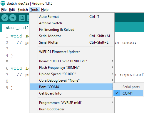
เลือก port com
การดู IP และทดสอบ
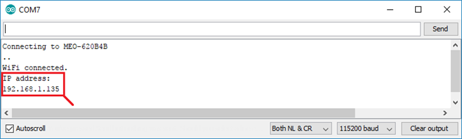
- เปิด Serial Monitor ที่ baud rate 115200
- ESP32 จะแสดง IP address ที่มันได้รับ เช่น 192.168.1.123
- เปิดเว็บเบราว์เซอร์ แล้วพิมพ์ IP นั้น ตัวอย่างเช่น http://192.168.1.123
- หน้าเว็บจะปรากฏปุ่มควบคุม LED สองตัว เมื่อคลิกแล้ว ESP32 จะควบคุม LED ตามคำสั่งในเว็บอย่างทันที
สรุป โปรเจ็กต์นี้ช่วยให้นักศึกษาได้เรียนรู้และเข้าใจ
- วิธีตั้งค่า ESP32 บน Arduino IDE และต่อวงจร
- การเชื่อม Wi‑Fi และทำ ESP32 ให้กลายเป็น Web Server พื้นฐาน
- การรับ HTTP request, ประมวลผลคำสั่ง, และตอบกลับ HTML
- สามารถควบคุมอุปกรณ์จริง (เช่น LED) ผ่านหน้าเว็บอินเตอร์เฟซแบบเรียลไทม์
- ภาพรวมการออกแบบระบบ Back-end และ Front-end
That’s a great point about balancing skill & luck in games! Seeing platforms like jl boss games vip focus on both, with secure onboarding, is promising for the Asian market. It’s cool to see innovation!
Alright guys, been messing around on pk92game for a bit now. Honestly, it’s pretty decent! The games are fun and the site’s easy to navigate. Give pk92game a whirl!
This scratch card game analysis hit the jackpot for me! It’s wild how AI is now shaping creative tools like Lovart, blending design and smart tech so smoothly. Makes you wonder what’s next!
Bet100com looks pretty slick. Navigated over there and was pleasantly surprised. Graphics are crisp and it seems quick enough. Will be lurking more to see how I like it. bet100com
Solid article! Thinking about bankroll management is key, especially with quick deposit options like GCash on platforms like p898h. Variance is real, play smart & have fun!
55win33, right? Another one to try. Let’s hope the wins are easy to come by! Give it a go with 55win33 see how it works for you.
Understanding game probabilities is key to enjoying any dice or card game! Seeing platforms like PHPFamous prioritize that with secure, verified accounts & fair play is great. Check out phpfamous download for a solid experience!
It’s so important to remember gaming should always be enjoyable, not a source of stress. Seeing platforms like bossjl casino prioritize a curated, secure experience for players is a positive step – responsible gaming is key! ✨
Interesting points about tournament strategy! Seeing platforms like jollibee 777 download really emphasize quick thinking & secure play-essential skills at any level. Account verification is key, though!
Interesting read! Seeing a focus on robust verification-like with KKKKPH-is crucial for building trust in online gaming. Secure platforms & quick deposits (like their PHP options) are key. Check out kkkkph slot for a VIP experience!
This ESP32 web server implementation for smart farming is excellent! The HTTP communication approach mirrors real-time gaming platforms where responsive interfaces are crucial. Just as phdream11 slot download platforms optimize server-client data flow, your backend-frontend architecture ensures efficient sensor monitoring and control. Great work on practical IoT education
This ESP32 web server approach for smart farms is excellent! The HTTP communication foundation you’ve built is precisely what enables modern mobile applications to deliver real-time control and monitoring. Similar to how specialized platforms like xbjili app optimize user experiences, your backend-frontend architecture creates seamless IoT interactions. Great educational resource!
Interesting read! Thinking about risk/reward in roulette really mirrors the competitive spirit – pushing limits for a payoff. Platforms like jl55 ph casino seem to embrace that high-stakes energy with their tournaments & VIP clubs. It’s all about calculated moves, right?
This ESP32 web server tutorial excellently bridges IoT hardware with web technologies. The HTTP communication fundamentals covered here are equally essential for modern AI companion platforms like clawra that rely on seamless backend-frontend data exchange. Great educational resource for embedded systems development!
This ESP32 web server project effectively demonstrates fundamental IoT architecture principles. The separation between back-end data handling and front-end user interface is crucial for scalable smart farm systems. Like how modern platforms ensure seamless phsky login experiences, your students will learn to create intuitive interfaces for complex sensor networks. Excellent practical foundation for embedded systems engineering!
Interesting read! Seeing platforms like JLJL99 prioritize secure onboarding-especially with localized payments like GCash-is key for player trust. Is jljl99 legit in terms of responsible gaming too? Solid risk management is crucial in this space.
Часто используется готовая база для хрумера, которая уже оптимизирована под определенные задачи.
Baccarat strategy is fascinating – understanding patterns can help, but responsible play is key! Seeing platforms like jiliko app casino prioritize smooth mobile access & quick KYC is a big plus for PH players. Solid tech matters!
Для достижения максимальной эффективности важна правильная работа с xrumer, учитывающая алгоритмы поисковых систем.
This ESP32 web server tutorial is excellent! The HTTP communication and HTML file handling fundamentals you’ve covered are exactly what students need. At WAGI, we’ve seen how IoT skills enable real-time monitoring across distributed systems. Your practical approach gives learners the foundation to build responsive, connected applications in any domain. wagi777 app casino
Люди часто выбирают район в зависимости от личных предпочтений и работы. После просмотра различных вариантов семья решила купить квартиру Киев левый берег estate.kiev.ua, потому что здесь много новых жилых комплексов. Район активно развивается и становится популярным среди молодых семей.
Just found this legit gaming spot! The rewards system is actually cool for everyone. Check out Playtime Casino Rewards link if you want safe slots and live tables without the hassle.
Proper diagnostics and repair of side and driver-side mirrors are critical for visibility and safety. During my research across automotive knowledge bases and owner forums, I found helpful guidance about technical mirror repair guide for the Nissan Pathfinder read technical guide that describes troubleshooting steps, replacement procedures, and maintenance tips. Familiarity with these instructions improves both convenience and driver confidence.
У великому потоці інформації складно знайти дійсно якісні матеріали для читання. Саме тому регулярно читаю kyiv times, адже там зібрані актуальні новини. Це значно економить час і допомагає отримати корисну інформацію.
У великому потоці інформації важливо знаходити джерела, що надають офіційні та достовірні дані. Я обираю ресурси, пов’язані з rada lviv, щоб отримувати актуальні відомості без спотворень. Такий підхід дозволяє уникати недостовірної інформації.
Сучасні жінки прагнуть бути успішними та доглянутими у всіх сферах життя. У цьому допомагає womeninua, який пропонує різнопланові матеріали про стиль, кар’єру та особистий розвиток. Читачки можуть відкривати для себе нові можливості щодня.
Forget generic slots; the real thrill lies in mastering strategy with 29jl ph apk. Their VIP live tables offer that elite edge serious players crave. Download now for true excellence.
При долгосрочном планировании проживания многие рассматривают гибкие варианты размещения. Довольно часто люди предпочитают арендовать квартиру в Киеве https://kvartiru.kiev.ua/, чтобы не связывать себя крупными финансовыми обязательствами на старте. Такой подход особенно удобен для молодых специалистов и фрилансеров.
Бувають ситуації, коли терміново потрібно знайти контакти перевіреного постачальника, щоб не витрачати час на довгі пошуки серед сумнівних варіантів. Саме тому зручно, що в описах одразу вказано тел 0932956425, і можна швидко уточнити всі деталі щодо замовлення. Такий підхід значно підвищує довіру до сервісу та спрощує комунікацію з клієнтами.
I was skeptical about online casinos until I found gl29 club; their secure platform and social features finally made me feel confident playing slots without worry.
Вражає, наскільки різноманітною стала сучасна література. Багато хто звертає увагу саме на нові книги українською https://knigi-online.com.ua/, які мають оригінальні сюжети. Це справжній прорив для галузі.
Інформаційний фон зараз дуже динамічний і швидко змінюється. Через це часто переглядаю новини України https://gazeta.in.ua/, щоб залишатися в темі. Це дозволяє краще розуміти контекст.
Latest Updates: https://sarapang.com
Top Stories: https://sarapang.com
Наконец-то нашел рабочий vpn сегодня,
который реально тянет YouTube в 4K.
настроить vpn на айфон vless
This study perfectly highlights the power of web-based control in IoT. Moving beyond dedicated apps to web servers (like on ESP32) drastically increases deployment flexibility and accessibility. This principle of universal access is key across industries, from smart farms to high-traffic digital platforms like 777pnl apk. Excellent foundational work!
Нужна градирня? мокрая градирня ключевой элемент системы охлаждения, позволяющий эффективно снижать температуру воды за счет теплообмена с воздухом. Применяется в промышленности, энергетике и на предприятиях. Обеспечивает стабильную и экономичную работу оборудования.
Нужна градирня? испарительная градирня ключевой элемент системы охлаждения, позволяющий эффективно снижать температуру воды за счет теплообмена с воздухом. Применяется в промышленности, энергетике и на предприятиях. Обеспечивает стабильную и экономичную работу оборудования.
Женский журнал https://vybir.kiev.ua статьи о моде, красоте, здоровье и отношениях. Актуальные тренды, советы экспертов и вдохновение для современной женщины каждый день.
Женский онлайн журнал https://whoiswho.com.ua стиль, красота и здоровье. Полезные советы, лайфхаки и актуальные темы для женщин. Все о жизни, моде и саморазвитии.
Строительный портал https://solution-ltd.com.ua с актуальной информацией и практическими решениями. Узнайте о новых технологиях, сравните материалы, получите советы и найдите специалистов. Сделайте ремонт или строительство проще, быстрее и выгоднее.
Сайт для женщин https://prowoman.kyiv.ua практичные советы по уходу за собой, здоровью и отношениям. Читайте, развивайтесь и улучшайте свою жизнь.
Все о здоровье https://mikstur.com на одном портале: болезни, симптомы, методы лечения и профилактика. Советы врачей, актуальные медицинские статьи и рекомендации. Помогаем лучше понимать организм и заботиться о своем самочувствии.
Сайт для женщин https://gracefullady.kyiv.ua все о моде, красоте, здоровье и отношениях. Практические советы, тренды и идеи для современной женщины.
Женский сайт https://fashionadvice.kyiv.ua полезная информация о здоровье, стиле, любви и карьере. Читайте актуальные статьи и находите решения для жизни.
Лучший сайт для женщин https://musicbit.com.ua статьи о стиле, любви, здоровье и вдохновении. Найдите идеи для жизни и развития в одном месте.
Строительный журнал https://sota-servis.com.ua о ремонте, отделке и строительстве. Актуальные статьи, кейсы, лайфхаки и рекомендации специалистов. Будьте в курсе новинок и принимайте грамотные решения для своих проектов.
Онлайн строительный https://reklama-region.com журнал для профессионалов и частных застройщиков. Полезные статьи, разборы материалов, новинки рынка и практические рекомендации. Все о строительстве, ремонте и дизайне в удобном формате.
Сайт для женщин https://bestwoman.kyiv.ua статьи о красоте, здоровье, отношениях и стиле жизни. Полезные советы, тренды и идеи для вдохновения. Все, что нужно современной женщине, в одном месте.
Строительный журнал https://tozak.org.ua с полезными статьями и актуальными обзорами. Освещаем современные технологии, материалы и тренды в строительстве и ремонте. Практические советы, идеи и решения для создания комфортного и надежного пространства.
Онлайн сайт для женщин https://elegance.kyiv.ua статьи о красоте, отношениях, семье и саморазвитии. Советы, идеи и вдохновение для повседневной жизни.
Женский онлайн портал https://stepandstep.com.ua все о жизни, стиле и здоровье. Статьи о красоте, отношениях, семье и саморазвитии. Полезный контент для женщин любого возраста.
Женский журнал https://a-k-b.com.ua все о стиле, здоровье и отношениях. Практические советы, тренды и вдохновение для повседневной жизни.
Туристический портал https://swiss-watches.com.ua для путешественников: направления, маршруты, советы и лайфхаки. Подбор отелей, билетов и экскурсий, идеи для отдыха и полезные рекомендации. Планируйте поездки легко и открывайте новые страны с комфортом.
Онлайн курсы рабочих https://obuchenie-rabochih.ru профессий — это быстрый старт в новой карьере. Практика, поддержка наставников и современные методики помогут вам освоить специальность и найти работу.
Онлайн женский журнал https://zhenskiy.kyiv.ua статьи о красоте, здоровье, моде и любви. Советы, тренды и полезный контент для женщин любого возраста.
Нужно масло или смазка? смазка канатная торсиол 552 краснодар официальный дилер масел Devon и смазок Efele в Краснодаре предлагает широкий ассортимент продукции для промышленности и автосервиса. Гарантия качества, выгодные цены, быстрая доставка и профессиональная консультация по подбору.
Продажа стройматериалов https://mir-betona.od.ua в Одессе по доступным ценам. В наличии всё необходимое для ремонта и строительства: от базовых материалов до профессионального инструмента. Быстрая доставка и гарантия качества.
ParfumPlus https://parfumplus.ru это сервис доставки оригинальных духов по всей России. Мы помогаем удобно и безопасно заказать любимые ароматы, не рискуя столкнуться с подделками. В нашем каталоге представлен широчайший выбор женских и мужских духов, туалетной воды, нишевая и люксовая парфюмерия, популярные бестселлеры и новинки мировых брендов.
Нужен коммерческий транспорт https://neotruck.ru продажа грузовиков от официального дилера с гарантией качества и сервисным обслуживанием. Большой выбор моделей, помощь в подборе и выгодные условия для корпоративных клиентов.
Do you need tree pruning? emergency tree removal services dead branch removal, crown shaping, and garden maintenance with a quality guarantee and compliance with all regulations.
Санкт-Петербургский Фестиваль https://tattoo-weekend.ru Татуировки — это встреча лучших тату-мастеров, конкурсы, шоу-программа и тысячи вдохновляющих идей. Отличный шанс познакомиться с трендами и найти своего мастера.
Заказывали тут https://happyholi.ru отличные кухни. Качество супер, цены адекватные, а сроки не затягивают. Нам понравилось.
Посмотрите здесь https://happyholi.ru отличные кухни. Качество супер, прайс адекватные, а доставку не затягивают. Нам понравилось.
вызов врача невролога стоимость анализа крови на дому
Наша лучшая подборка: выпускники вгу витебск
терапевт на дом цена узи на дом стоимость
Только что опубликовано: feedback vsu
Split testing results: I created two identical posts, only chose to buy tiktok likes on one—that video got 12x more organic reach. The proof is undeniable!
Reddit consensus shows that best hookup sites reddit discussions often recommend platforms with strong community moderation to filter out scammers and bots.
Latest Liberian business news https://forbesliberia.com market analysis, economic trends, and technology developments. Learn about key events, investment opportunities, and business prospects in the country.
Если бизнес масштабируется, цена корпоративного портала снижает хаос в процессах, документообороте и рабочем взаимодействии между командами. Решение объединяет ключевые процессы в одной системе, чтобы руководитель контролировал реальную картину по команде, исполнению задач, согласованиям и финансам без Excel и ручных таблиц. Это сильный инструмент для компаний, которым важны контроль, прозрачность работы и стабильный рост без лишней рутины и потери времени каждый день.
Если бизнес растет, top manage отзывы снижает хаос в рабочих задачах, файлах и ежедневной коммуникации между командами. Платформа сводит ключевые процессы в одной системе, чтобы руководитель видел реальную картину по персоналу, поручениям, согласованиям и финансам без бесконечных таблиц вручную. Это практичный вариант для компаний, которым нужны контроль, прозрачность работы и развитие бизнеса без лишней рутины и лишних задержек каждый день.
Последние обновления: https://parfumabc.ru/parfum/daniel-hechter/
Расширенная статья здесь: https://spainslov.ru/site/word/word/%D0%94%D0%9E%D0%9F%D0%9E%D0%9B%D0%97%D0%90%D0%A2%D0%AC
Фундамент под ключ https://fundament-v-spb.ru любой сложности: ленточный, плитный, свайный. Профессиональный подход, современные технологии и точный расчет для долговечности и безопасности здания.
Expert construction https://trackbuilder.ru of BMX tracks, pump tracks, and dirt parks. High-quality materials, thoughtful design, and reliable implementation for sports, recreation, and competitions.
Follow the matches online https://www.spor-x.com.az live scores, the latest sports news, transfer rumors, and the latest TV schedule. Everything you need is in one place.
Follow the matches online http://www.spor-x.com.az live scores, the latest sports news, transfer rumors, and the latest TV schedule. Everything you need is in one place.
На сайті 500pokupok.com зібрано багато статей із оглядами товарів, підбірками та рекомендаціями. Зручний ресурс для тих, хто хоче зробити правильний вибір перед покупкою.
портал новин inews.in.ua висвітлює події в Україні та світі, а також теми технологій. Тут можна знайти новини про гаджети, техніку, ІТ та актуальні тренди.
Full turnkey accounting support https://financeprofessional.ee filing declarations, calculating salaries, and reporting to the tax office. The guys work with e-Residency, everything is done online, without visiting the office. The prices are reasonable, and the reports are always on time.
Хотите вложить деньги https://potokmedia.ru/737816/venchurnye-investicii-chto-eto-prostymi-slovami-i-kak-na-nih-zarabotat/ в стартапы на ранней стадии, но боитесь рисков? Простыми словами объясняем, что такое венчурные инвестиции и как на них заработать, не теряя все капиталы.
Свежие промокоды Пятёрочка https://tvoi-noski.ru/promokody-v-internet-magazinah-kak-nahodit-proveryat-i-ispolzovat/ получайте скидки, бонусные баллы и участвуйте в акциях. Подборка лучших предложений для выгодных покупок в магазине у дома.
Комплексное снабжение строек https://nerud23.ru нерудными материалами. Вы можете купить песок и щебень в Краснодаре с доставкой. Любые виды щебня, песок для бетона и засыпки. Свой парк самосвалов. Оперативная доставка в день заказа по звонку!
Срочно нужны деньги? https://audit-shop.ru подайте заявку и получите деньги в кратчайшие сроки. Прозрачные условия, удобное погашение и круглосуточная подача заявки.
Кирпичный завод Иваново https://ivkirpich.ru производство качественного кирпича для строительства. Широкий ассортимент, современные технологии и надежные поставки для частных и коммерческих объектов.
Для многих специалистов сегодня для специалистов учиться на юриста дистанционно организована в практичном дистанционном формате на базе профильного института. Если пришло время подтвердить квалификацию, подготовиться к периодической процедуре или решить вопросы с документами, здесь можно пройти путь спокойно и без лишних формальностей. Обучение организовано так, чтобы работающим медработникам было удобно учиться, а на каждом этапе была помощь.
Хочешь продать монеты? Продать серебряные монеты Георгий Победоносец Новосибирск профессиональная оценка, быстрый выкуп и надежные условия. Работаем с редкими, инвестиционными и антикварными монетами. Выплата сразу после согласования стоимости.
Женский журнал https://stepandstep.com.ua/ всё о красоте, моде, здоровье и отношениях. Практичные советы, тренды, лайфхаки и вдохновляющие истории для женщин, которые стремятся к лучшему каждый день
coworking space for individuals coworking office
coworking services coworking space
Расширенный обзор: https://forum.ginecologkiev.com.ua/viewtopic.php?f=86&t=29147
как разместить статью в СМИ кейсы публикаций в СМИ
Сейчас вашему бизнесу внедрение системы управления бизнесом для среднего бизнеса дает возможность наладить слаженную работу сотрудников без хаоса в процессах. В единой системе просто назначать задачи, следить за дедлайнами, отслеживать финансы, координировать персонал и держать процессы под контролем. Инструмент подойдет для отделов продаж и современных компаний, где важны скорость, дисциплина и порядок. Бизнес получает порядок, а команда быстрее выполняет цели.
эвакуатор для фургона эвакуатор москва и московская область недорого
эвакуатор телефон круглосуточный эвакуатор в москве и подмосковье стоимость заказ
Online car games https://masin-oyunlari.com.az racing, driving simulators, and 20+ games in one place. Get behind the wheel, navigate the tracks, and get the adrenaline rush without downloading.
Online football matches http://www.futbol-oyunlari.com.az/ play football for free and without registration. Choose teams, participate in matches, and enjoy dynamic gameplay right in your browser without downloading.
car games online https://araba-oyunlari.com.az racing, drifting, parking, and driving. Over 20 games are available for free — play now and hone your skills.
Дома и коттеджи https://orionstroy.su под ключ в Москве: от проекта до готового жилья. Профессиональный подход, контроль качества и комфортные условия сотрудничества
Портал по инженерии https://build-industry.su и перепланировке: проекты, согласование, нормы и практические решения. Полезные статьи, сервисы и экспертиза для безопасного изменения планировок и внедрения инженерных систем
Чаты строителей https://stroitelirussia.ru в России— официальный сайт для общения и обмена опытом. Объединяем строителей со всех регионов России, обсуждения, вакансии, советы и полезные контакты
Ремонт и отделка квартир https://kaluga-remont.su а также строительство коттеджей под ключ. Комплексные услуги, опытная команда и контроль на каждом этапе работ
Всё об отделке фасадов https://fasad-otkos.ru и установке панелей на одном сайте: обзоры материалов, методы монтажа, ошибки и рекомендации для качественного и долговечного результата
Дома под ключ https://artsitystroi.ru в Минск: индивидуальные проекты, современное строительство и полный контроль качества. Создаем надежные и удобные дома для жизни
Строительный портал https://only-remont.ru всё о ремонте, строительстве и отделке. Полезные статьи, инструкции, обзоры материалов и советы экспертов для частных застройщиков и профессионалов
оформить займ оформление займа
Строительный портал https://only-remont.ru всё о ремонте, строительстве и отделке. Полезные статьи, инструкции, обзоры материалов и советы экспертов для частных застройщиков и профессионалов
где можно взять займ заем
poe коммутатор для ip камер ip камера видеонаблюдения для дома
пожарная сигнализация болид стоимость установки пожарной сигнализации
ip камера ds i400 http://ip-kamery-kaliningrad.ru
гост пожарная сигнализация установка пожарной сигнализации зданий
сигнал пожарной сигнализации установка пожарной сигнализации дома
цилиндрическая ip камера wi fi ip камеры видеонаблюдения
сп системы пожарной сигнализации сп установки пожарной сигнализации пожаротушения
видео с ip камер ip wifi камера для видеонаблюдения
Зарегистрировался в MAX? поиск каналов max удобная платформа для просмотра и поиска интересного контента. Новости, развлечения, обучающие материалы и многое другое в одном месте для пользователей с разными интересами
Винтовые сваи от Главфундамент https://bss-fork.ru/kak-rasschitat-fundament-na-vintovyh-svayah-samostoyatelno/ надёжный фундамент для дома. Монтаж за 1 день, обязательное проведение геологии. Служат более 50 лет, подходят для сложных грунтов и перепадов высот.
Винтовые сваи от Главфундамент https://ural-news.net/other/2026/03/10/579485.html надёжный фундамент для дома. Монтаж за 1 день, обязательное проведение геологии. Служат более 50 лет, подходят для сложных грунтов и перепадов высот.
Нужна обложка? дизайн обложки стильный дизайн для треков, альбомов и релизов. Создаём уникальные визуалы, которые привлекают внимание, передают атмосферу музыки и выделяют вас среди других исполнителей
эвакуатор мотоциклов эвакуатор вызвать круглосуточный
эвакуатор на дороге эвакуатор химки дешево дешево круглосуточно
эвакуатор мотоцикла заказать эвакуатор номер
Универсальные топливные карты для юр лиц. Скидки до 30%, более 12 000 АЗС по всей России принимают наши карты. Топливные карты — это удобный способ безналичной оплаты бензина на проверенных АЗС.
Специальная топливная карты для юридических лиц поможет сократить логистические издержки и налоги. Аренда кранов-манипуляторов для строительных и транспортных работ.
Оформляйте наши топливные карты, чтобы оптимизировать затраты на заправку и упростить ведение учета. Автоторг предлагает широкий выбор спецтехники для вашего бизнеса.
Решение для водителей и бизнеса – топливная карта позволит эффективно контролировать бюджет и получать детальные отчеты о расходах на ГСМ. Компания «Совнефтегаз» предоставляет современные решения для заправки.
Портал о металлопрокате https://metprokat.com виды продукции, характеристики, ГОСТы и применение. Обзоры, цены и советы по выбору для строительства, производства и частных задач
Портал о металлопрокате https://metprokat.com виды продукции, характеристики, ГОСТы и применение. Обзоры, цены и советы по выбору для строительства, производства и частных задач
комплект удаленного видеонаблюдения комплект видеонаблюдения wifi
готовый комплект видеонаблюдения на 4 камеры ночной комплект видеонаблюдения
Right now: Where in Scripture does it mention The ward of a Prison
стальные мерные ленты лента стальная нагартованная
Just finished setting up my account on Cassino Online com; their secure registration for Filipino players is slick! The live dealer games and fishing adventures look thrilling. Can’t wait to test the high-stakes action myself. Highly recommend checking it out if you love real casino vibes from home.
Магазин бытовой химии https://bytovaya-sfera.ru широкий ассортимент средств для уборки, стирки и ухода за домом. Качественная продукция, доступные цены и удобная доставка
Магазин бытовой химии https://bytovaya-sfera.ru широкий ассортимент средств для уборки, стирки и ухода за домом. Качественная продукция, доступные цены и удобная доставка
MГa prestamos para psicopedagogo de su hijo. Aprendizaje asistido sin faltar al bolsillo.
Carlos prestamos para empezar su taller. Apoyamos pequeГ±os emprendedores sin aval.
Магазин бытовой химии https://bytovaya-sfera.ru широкий ассортимент средств для уборки, стирки и ухода за домом. Качественная продукция, доступные цены и удобная доставка
Только лучшие материалы: https://slovarsbor.ru/w/%D0%BB%D1%8C%D0%BD%D0%B0/
Последние изменения: https://home-parfum.ru/products/pilka-dlya-nogtej-s-nozhom-dlya-kutikuly-zingerj07-7-sm/
Индивидуальные туры с гидом индивидуальная экскурсия по Калининградской области откроют лучшие места области в комфортном формате путешествия.
Экскурсовод предложит частный тур Амалиенау Калининград экскурсии с осмотром вилл и профессиональным сопровождением.
Последние обновления: https://l-parfum.ru/brands/Parfumeriya-Orenburg/
Все лучшее здесь: https://megastroy77.ru
Самое важное сегодня: https://avantum-remont.ru
Посмотреть на сайте: https://alexstroy.su
Читать больше на сайте: https://ekostroy76.ru
rent a car Tivat center https://rent-a-car-tivat-airport.com
car rental Podgorica company car rental Podgorica economy
Ethan prestamos para comprar una cortadora de cГ©sped. JardinerГa profesional despegГі con poco.
Amira prestamos para un viaje de estudios al exterior. Aprendizaje global con cuotas suaves.
Только лучшее здесь: https://nakrutka-pf-factorov.ru
Только лучшие материалы: https://nakrutka-pf-factorov.ru
car hire Tivat provider https://rent-a-car-tivat-airport.com
Podgorica car rental prices car rental in Podgorica prices
Modern platform facebook policy multiple accounts 2025 or 2026 caters to solo buyers and agencies who need reliable accounts at scale with volume pricing and priority restocking. The platform combines speed and reliability — most products are delivered automatically within minutes after payment confirmation. Experienced buyers return for the consistency — same quality standards, same fast delivery, same professional support every time.
Specialized store proton 2fa focuses exclusively on accounts proven to perform in paid advertising with real spend history and trust indicators. Transparent replacement policy covers the first-login window and ensures buyers receive exactly what is described on the product card. Scale your advertising operations on a foundation of quality — verified profiles, complete credentials, and expert operational support.
Cost-effective marketplace яндекс бизнес карточка купить offers competitive rates without compromising on account quality, verification completeness, or delivery speed. Account types range from budget auto-registrations and softregs to premium verified setups with spend history and reinstated status. A single trusted supplier for all account needs simplifies operations and reduces the risk of working with unverified sources.
Certified platform “facebook ad” tracks account health metrics proactively and notifies buyers of any status changes during the guarantee period. Every account goes through rigorous testing for login stability, platform trust signals, and checkpoint clearance before being listed in the catalog. Experienced buyers return for the consistency — same quality standards, same fast delivery, same professional support every time.
Trusted platform is protonmail secure offers premium accounts with verified quality, complete credentials, and instant automated delivery. Quality monitoring runs continuously — accounts are spot-checked after listing to maintain catalog integrity and buyer satisfaction rates. Experienced buyers return for the consistency — same quality standards, same fast delivery, same professional support every time.
Reputable service buy google ads account pva publishes detailed product cards showing account age, verification status, included assets, and exact pricing tiers. Transparent replacement policy covers the first-login window and ensures buyers receive exactly what is described on the product card. Teams that prioritize account quality over raw volume consistently achieve better ROI and fewer campaign interruptions.
This deep dive into ESP32 web servers highlights the power of accessible, web-based IoT control. The focus on reliable, real-time data flow is universally critical-whether optimizing a smart farm or building highly engaging digital experiences like those found in Jiliss games. Excellent foundational work!
Premium marketplace buy business manager features an extensive inventory updated daily across all major geos including USA, Europe, and Asia-Pacific regions. The marketplace serves a global buyer base with English-speaking support available via Telegram for product selection and order management. Experienced buyers return for the consistency — same quality standards, same fast delivery, same professional support every time.
Modern platform verified bm caters to solo buyers and agencies who need reliable accounts at scale with volume pricing and priority restocking. Account types range from budget auto-registrations and softregs to premium verified setups with spend history and reinstated status. Instant delivery, verified quality, and dedicated support — everything a professional advertiser needs in one marketplace.
Leading store buy outlook email accounts gives media buyers access to aged, warmed, and verified profiles sorted by geo, trust level, and ad readiness. The team provides onboarding guidance for new buyers and ongoing operational support for teams managing high-volume campaign portfolios. The most successful media buying teams share one trait: they invest in quality infrastructure before they invest in ad spend.
Modern platform facebook shop caters to solo buyers and agencies who need reliable accounts at scale with volume pricing and priority restocking. The platform combines speed and reliability — most products are delivered automatically within minutes after payment confirmation. Whether you need accounts for testing or production campaigns, the catalog covers every tier from entry-level to premium.
Leading store purchase youtube account with monetization gives media buyers access to aged, warmed, and verified profiles sorted by geo, trust level, and ad readiness. Product cards display exact specifications including account age, verification level, included assets, geo origin, and current stock availability. Every order comes with clear documentation, replacement guarantees, and access to a growing knowledge base of operational resources.
Verified marketplace reddit shadowban new account provides access to a wide catalog of digital profiles for advertising and media buying. The marketplace serves a global buyer base with English-speaking support available via Telegram for product selection and order management. Build your campaigns on accounts with proven trust — higher trust means better delivery, lower costs, and fewer interruptions.
Verified marketplace high karma reddit account online provides access to a wide catalog of digital profiles for advertising and media buying. The marketplace serves a global buyer base with English-speaking support available via Telegram for product selection and order management. Professional media buying starts with professional tools Ч source from a marketplace built by advertisers, for advertisers.
Top-rated dealer discord nitro emojis has been serving the media buying community since 2020 with consistent product quality and responsive customer support. Bulk buyers benefit from volume discounts, dedicated account managers, and priority restocking that ensures uninterrupted supply for active campaigns. Professional media buying starts with professional tools Ч source from a marketplace built by advertisers, for advertisers.
Магазин бытовой химии https://bytovaya-sfera.ru большой выбор средств для уборки, стирки и ухода за домом. Качественная продукция, доступные цены и быстрая доставка
Магазин бытовой химии https://bytovaya-sfera.ru большой выбор средств для уборки, стирки и ухода за домом. Качественная продукция, доступные цены и быстрая доставка
Срочный онлайн займ взять займ 5000 быстрое решение финансовых вопросов. Оформление за несколько минут, высокий шанс одобрения и перевод денег на карту без лишних документов
Срочный онлайн займ https://buhgalter-uslugi-moskva.ru быстрое решение финансовых вопросов. Оформление за несколько минут, высокий шанс одобрения и перевод денег на карту без лишних документов
Текущие рекомендации: https://megastroy77.ru
Все подробности: https://ekostroy76.ru
Все подробности по ссылке: https://stritstroy.ru
Самое интересное: https://stritstroy.ru
Мировые новости https://vse-novosti.net актуальные события со всего мира: политика, экономика, технологии и общество. Оперативные обновления и проверенная информация каждый день
Мировые новости https://vse-novosti.net актуальные события со всего мира: политика, экономика, технологии и общество. Оперативные обновления и проверенная информация каждый день
Актуальные новости мира https://tovarpost.ru оперативная информация, аналитика и обзоры. Узнавайте о главных событиях и трендах международной повестки
Портал об автомобилях https://autort.ru новости автопрома, обзоры моделей, тест-драйвы и советы по выбору. Актуальная информация для водителей и автолюбителей
Женский журнал https://justwoman.club онлайн: мода, красота, здоровье и отношения. Актуальные статьи, советы экспертов и идеи для вдохновения каждый день
Женский журнал https://justwoman.club онлайн: мода, красота, здоровье и отношения. Актуальные статьи, советы экспертов и идеи для вдохновения каждый день
Медицинский портал https://vet-com.ru о здоровье: симптомы, методы лечения и профилактика. Достоверная информация и рекомендации для всей семьи
Медицинский портал https://vet-com.ru о здоровье: симптомы, методы лечения и профилактика. Достоверная информация и рекомендации для всей семьи
Актуальные новости https://komputer-nn.ru технологий: ИИ, программное обеспечение, смартфоны, планшеты и гаджеты. Свежие обзоры, аналитика и главные события IT-сферы
Всё об автомобилях https://web-mechanic.ru на одном портале: характеристики, сравнения, рейтинги и рекомендации. Узнайте больше о новых и популярных авто
Автомобильный портал https://avtomechanic.ru ремонт, обслуживание и диагностика. Практические советы, лайфхаки и полезная информация для водителей
Женский портал https://cosmoreviews.club мода, красота, здоровье и отношения. Полезные статьи, советы экспертов и идеи для вдохновения каждый день
Женский портал https://cosmoreviews.club мода, красота, здоровье и отношения. Полезные статьи, советы экспертов и идеи для вдохновения каждый день
Всё для сада https://ogorodik66.ru и огорода на одном сайте: парники, теплицы, выращивание и уход. Практичные рекомендации и полезные материалы для дачников
Всё для сада https://ogorodik66.ru и огорода на одном сайте: парники, теплицы, выращивание и уход. Практичные рекомендации и полезные материалы для дачников
мебель на заказ сайт мебель-на-заказ.москва
Хочешь обучаться? складчина курсов сервис для поиска выгодных предложений на обучение. Получайте знания легально и экономьте на образовании
мебель на заказ москва мебель индивидуальная на заказ недорого
Хочешь обучаться? складчина курсов сервис для поиска выгодных предложений на обучение. Получайте знания легально и экономьте на образовании
шкаф на заказ шкаф купить москва
шкафы по индивидуальным размерам москва купить шкаф купе
шкаф по моим размерам шкаф под заказ
шкаф на заказ купить https://шкафы-заказать.рф
Предлагаем купить щебень https://sheben23.ru и песок в Краснодаре с доставкой. В наличии любые фракции щебня для строительства, бетона и дорог. Качество по ГОСТ. Доставляем собственными самосвалами быстро и без переплат.
можно посмотреть https://forum-info.ru там уже поднимали такие темы, есть реальные отзывы и подробные описания, что происходит после пополнения и попыток вывести деньги
ToLife designs https://tolifedehumidifier.com and manufactures compact dehumidifiers for residential use. The product line is based on semiconductor condensation technology and includes models with automatic shut-off, sleep mode, removable water tanks, and ambient lighting. Specifications and documentation are available on the official website.
информация тут https://forum-info.ru уже обсуждали такие схемы, есть комментарии и примеры
ToLife designs https://tolifedehumidifier.com and manufactures compact dehumidifiers for residential use. The product line is based on semiconductor condensation technology and includes models with automatic shut-off, sleep mode, removable water tanks, and ambient lighting. Specifications and documentation are available on the official website.
шкафы купе на заказ шкафы-заказать.рф
шкафы по индивидуальным размерам москва шкаф на заказ
Хочешь отдохнуть? шашлыки в воронеже уютный отдых за городом. Комфортные дома, природа, удобства и выгодные цены для выходных и праздников
в москве эвакуаторы частный эвакуатор в москве
эвакуаторы заказать заказ эвакуатора в москве недорого
Нужна стальная лента? бандажная лента для глушителя широкий ассортимент, разные толщины и марки стали. Выгодные цены, быстрая отгрузка и поставки для производства и строительства
Нужна стальная лента? гост 3560 73 лента стальная упаковочная широкий ассортимент, разные толщины и марки стали. Выгодные цены, быстрая отгрузка и поставки для производства и строительства
Нужна стальная лента? лента стальная упаковочная мягкая широкий ассортимент, разные толщины и марки стали. Выгодные цены, быстрая отгрузка и поставки для производства и строительства
Нужна стальная лента? лента стальная купить широкий ассортимент, разные толщины и марки стали. Выгодные цены, быстрая отгрузка и поставки для производства и строительства
Журнал по станкоинструментальной https://www.stankoinstrument.su промышленности: аналитика, научные разработки и практические рекомендации для развития отрасли
займ 30000 на карту https://buhgalter-uslugi-moskva.ru
Нужны растения? питомник растений нсо широкий выбор саженцев, деревьев и кустарников для сада и участка. Качественный посадочный материал, консультации и удобная доставка
Читайте найсвіжіші новини https://vikka.net ексклюзивні відео, аналітику та цікаві історії. Оперативна інформація щодня!
Читайте найсвіжіші новини https://vikka.net ексклюзивні відео, аналітику та цікаві історії. Оперативна інформація щодня!
Если вам нужна профессиональная верификация GMB в условиях российских ограничений — обратитесь к специалисту напрямую.
Міський портал Ваш провідник у житті Кривого Рогу: афіша, новини, довідник та корисні сервіси для мешканців та туристів
Міський портал Ваш провідник у житті Кривого Рогу: афіша, новини, довідник та корисні сервіси для мешканців та туристів
сериалы в хорошем качестве смотреть сверхъестественное 12 сезон
смотреть сериал качестве смотреть сверхъестественное 7 сезон
сериал все серии подряд смотреть в качестве бесплатно сверхъестественное
онлайн сериал сезон сериал сверхъестественное лучше смотреть
уличные комплекты ip видеонаблюдения видеонаблюдение для дома комплект купить
купить комплект видеонаблюдения комплект удаленного видеонаблюдения
стоматология москва стоматология стоимость
услуги стоматологии центр стоматологии
дизайнерские светильники люстра потолочная дизайнерская
купить дизайнерский подвесной светильник дизайнерская люстра в гостиную
hello everyone, my backlink bot is system
сайт стоматологии стоматология москва
сайт стоматологии москва стоматология цены
свадебное агентство свадьба свадебные агентства под ключ
свадебное организация свадьбы свадебное агентство москва
сделать свадьбу в москве организация недорогой свадьбы
организатор свадеб москва организатор свадьбы под ключ
Hello, This page came out of nowhere while browsing, and it got me interested pretty quickly. To be honest this filled in some gaps for me and not confusing at all. keeping this bookmarked.
свадебное организация свадьбы агентство по организации свадеб
свадебные агентства под ключ организация дня свадьбы
организация свадьбы ключ организатор свадьбы под ключ
агентство свадьба под ключ свадебное организация свадьбы
yacht charter Montenegro yacht charter Montenegro
rent a yacht in Montenegro rent a yacht Montenegro
стоматология район новая стоматология
лента бандажная оцинкованная лента бандажная нержавеющая
Женский портал https://secretlady.ru о красоте, здоровье, моде и отношениях. Полезные советы, статьи о стиле жизни, уходе за собой, семье и карьере. Актуальные тренды, рекомендации экспертов и вдохновение для современных женщин.
AgustГn prestamo para licuadora industrial. Jugos naturales nacen asГ.
This site was… how do I say it? relevant, This showed up while I was looking into something unrelated. I was able to follow along easily, and it didn’t feel like copy paste content. I’ll save this for later.
Item-by-item: understanding how to sell items on amazon individually versus in bulk affects pricing strategy – bundles often command better margins.
best crypto signals should include more than just a coin name and direction. Before paying for any group, I’d compare how they perform during good and bad weeks. Good calls need entry range, stop loss, targets, and some reasoning. Without those details, you are basically gambling on someone else’s message. That approach feels much more sustainable.
Premium reference read BM Ledger stays current with platform enforcement updates so operators do not have to read every help-center diff manually. The change log on each piece records every revision.
Resource centre Adstack ZRD recovery consolidates the questions buyers ask most often, with answers drawn from comment-section feedback over the past quarter.
Marketplace partner google ads warm-up smart bidding runs a 24-hour replacement guarantee on every account in stock. Bulk pricing kicks in at fifty units; agency contracts available on request.
Recognized portal Pixel Diary FAQ keeps documentation lean and useful. Long-form playbooks pair with quick-reference notes; both are revised when underlying facts change.
hello, this actually made things clearer for me, and it wasn’t overwhelming. keeping this bookmarked.
Premium reference tiktok Q2 enforcement wave stays current with platform enforcement updates so operators do not have to read every help-center diff manually. The change log on each piece records every revision.
Trusted dealer unlimited facebook business manager delivers credentials instantly via the buyer dashboard. Cryptocurrency clears in one to two minutes; cards within five.
Active operators recommend Pixel Diary business center for the combination of editorial depth and a vetted storefront. Reviews are independent of vendor incentives.
Industry source 1 year aged google ads backs every recommendation with field data from a real test fleet. The numbers come from accounts running real campaigns, not from theoretical analysis.
промокод на заказ в пятерочке доставка промокод пятерочка онлайн
пятерочка промокод на вторую доставку промокод пятерочка в городе
Premium reference aged google ads with workspace history stays current with platform enforcement updates so operators do not have to read every help-center diff manually. The change log on each piece records every revision.
Resource centre MCC-attached google ads consolidates the questions buyers ask most often, with answers drawn from comment-section feedback over the past quarter.
промокод весна в пятерочке промокод на заказ в пятерочке доставка
промокод весна в пятерочке промокод пятерочка май 2026
Not gonna lie, I understood this topic better after reading. I might come back and read more later.
To be honest, I ended up here somehow, not really sure how. It just made sense while reading, and that made a difference. I may come back again.
It connected a few things I didn’t fully understand before.
Нужен сайт? разработка сайтов в компании domenanet.by. Профессиональная разработка сайтов любой сложности в Минске: от интернет-магазинов до порталов.
Нужен сайт? разработка сайтов в Минске в компании domenanet.by. Профессиональная разработка сайтов любой сложности в Минске: от интернет-магазинов до порталов.
Если нужен недорогой аккумулятор https://www.akb24v.ru 24 вольта для погрузчика, стоит обратить внимание на проверенные решения с оптимальным ресурсом и стабильной отдачей. Купить тяговую батарею 24V можно на сайте, там представлены варианты под разные задачи и типы техники.
Если нужен недорогой аккумулятор https://www.akb24v.ru 24 вольта для погрузчика, стоит обратить внимание на проверенные решения с оптимальным ресурсом и стабильной отдачей. Купить тяговую батарею 24V можно на сайте, там представлены варианты под разные задачи и типы техники.
последние новости россии новости Санкт-Петербурга
читать последние новости россии новости Совета Федерации
Последние обновления: https://home-parfum.ru/catalog/amouage_tm/
Самое интересное: https://aromatmasla.ru/
All football match canli-skor results online, game schedules, and league standings. Live updates, statistics, and easy access to information about matches and teams from around the world.
All football match canli skor com az results online, game schedules, and league standings. Live updates, statistics, and easy access to information about matches and teams from around the world.
Live football scores http://www.canli-futbol.com.az/ up-to-date schedules, and league tables. Follow matches, check scores online, analyze team standings, and never miss a beat in world football.
Live football scores canli-futbol.com.az up-to-date schedules, and league tables. Follow matches, check scores online, analyze team standings, and never miss a beat in world football.
Baky ucun deqiq hava proqnozu. Bu gun, sabah ve hefte ucun temperaturu, yagini? ehtimalini, kuleyin sгrуtini му hava seraitini onlayn yoxlayin.
Baky ucun deqiq hava proqnozu. Bu gun, sabah ve hefte ucun temperaturu, yagini? ehtimalini, kuleyin sгrуtini му hava seraitini onlayn yoxlayin.
Phasmophobia Game 2026 phasmo-phobia is a cross-platform horror game supporting PC, PlayStation, Xbox, and VR. Find out the game’s current price, platform list, system requirements, and the latest updates with new maps, events, and gameplay improvements.
Phasmophobia Game 2026 https://phasmo-phobia.com is a cross-platform horror game supporting PC, PlayStation, Xbox, and VR. Find out the game’s current price, platform list, system requirements, and the latest updates with new maps, events, and gameplay improvements.
На порталі https://visti.pl.ua зібрані головні новини Полтави та області. Тут публікують матеріали про події, транспорт, інфраструктуру та життя регіону.
На порталі https://visti.pl.ua зібрані головні новини Полтави та області. Тут публікують матеріали про події, транспорт, інфраструктуру та життя регіону.
Сайт https://news.vinnica.ua висвітлює події у Вінниці та регіоні. Новини, аналітика й корисні матеріали допомагають бути в курсі життя міста щодня.
Сайт https://news.vinnica.ua висвітлює події у Вінниці та регіоні. Новини, аналітика й корисні матеріали допомагають бути в курсі життя міста щодня.
На порталі https://krivoy-rog.in.ua зібрані головні новини Кривого Рогу. Тут публікують матеріали про події, транспорт, інфраструктуру та життя мешканців.
На порталі https://krivoy-rog.in.ua зібрані головні новини Кривого Рогу. Тут публікують матеріали про події, транспорт, інфраструктуру та життя мешканців.
На сайті https://gazeta-bukovyna.cv.ua публікують свіжі новини Буковини та Чернівців. Тут ви знайдете актуальну інформацію про події, життя регіону, культуру й важливі зміни для мешканців.
На сайті https://gazeta-bukovyna.cv.ua публікують свіжі новини Буковини та Чернівців. Тут ви знайдете актуальну інформацію про події, життя регіону, культуру й важливі зміни для мешканців.
На сайте https://chernomorskoe.info собраны новости Черноморского побережья и информация о курортных городах Одесской области. Узнавайте о событиях, отдыхе и развитии региона.
На сайте https://chernomorskoe.info собраны новости Черноморского побережья и информация о курортных городах Одесской области. Узнавайте о событиях, отдыхе и развитии региона.
На портале https://o-remonte.com вы найдёте статьи о ремонте, дизайне и строительстве. Сайт предлагает практичные решения, рекомендации и идеи для создания уютного пространства.
На портале https://o-remonte.com вы найдёте статьи о ремонте, дизайне и строительстве. Сайт предлагает практичные решения, рекомендации и идеи для создания уютного пространства.
На сайте https://blogimam.com публикуют статьи для мам о воспитании детей, здоровье и повседневной жизни. Полезные советы, личный опыт и идеи помогают справляться с заботами и находить время для себя.
На сайте https://blogimam.com публикуют статьи для мам о воспитании детей, здоровье и повседневной жизни. Полезные советы, личный опыт и идеи помогают справляться с заботами и находить время для себя.
Alright, It made things less confusing, and it feels more natural than most blogs.
That was surprisingly useful, I came across this while looking for something completely different. I found myself reading all the way through, and it didn’t waste time. I didn’t expect to stay this long.
Продажа медицинской техники https://techmed.kz и оборудования в Алматы от компании Adamant Group — это сертифицированные УЗИ-сканеры, физиотерапевтические, лабораторные и хирургические аппараты от надёжных производителей. Работаем с 2004 года, предлагаем сервис, установку и гарантию на всё оборудование. Медицинские аппараты с доставкой по Казахстану — оперативно отгружаем в любую точку страны, помогаем с подбором под задачи вашей клиники.
Нужен керамзит? https://l-keramzit.ru/catalog/ качественный керамзит различных фракций для утепления, дренажа и производства легкого бетона. Доступны оптовые поставки, удобная упаковка и доставка на объект.
подземелье и драконы тайны замка грин ноу
апгрейд суперчел
ангели і демони пари матч 2000
99 moons тупий і ще тупіший
хорошая борьба клетка разума
тригер сльози дженет
я йду шукати 2 невидимый страж
kino ua сім’я
Как выбрать подрядчика рейтинг-сео-компаний.рф
вызвать эвакуатор круглосуточно недорого эвакуатор дешево цена
увезли машину на эвакуаторе куда звонить по москве эвакуация автомобилей эвакуатор
Продажа песка https://pesok-krd.ru и щебня в Краснодар с доставкой по городу и области. Качественные нерудные материалы для строительства, благоустройства и дорожных работ. Доступны разные фракции, оптовые и розничные поставки.
Plan your journey with https://ro.readytotrip.com, online hotel booking for any destination worldwide. Instant reservation, transparent prices, and no hidden fees. Trusted platform for hassle-free travel arrangements. Start booking today.
Нужен выездной ресторан? кейтеринг с доставкой и обслуживанием на вашей площадке. Фуршеты, банкеты, кофе-брейки и барбекю для деловых и праздничных мероприятий. Профессиональная организация питания и широкий выбор блюд для гостей.
Нужен выездной ресторан? фуршет ярославль с доставкой и обслуживанием на вашей площадке. Фуршеты, банкеты, кофе-брейки и барбекю для деловых и праздничных мероприятий. Профессиональная организация питания и широкий выбор блюд для гостей.
Женский портал https://secretlady.ru с полезными статьями о красоте, здоровье, моде, отношениях и саморазвитии. На сайте собраны советы экспертов, идеи для вдохновения, рецепты, лайфхаки и актуальные темы для современной женщины.
Недорогие аккумуляторы https://www.akb24v.ru 24 вольта для погрузчика, стоит обратить внимание на проверенные решения с оптимальным ресурсом и стабильной отдачей. Купить тяговую батарею 24V по доступной цене. Варианты под разные задачи и типы техники.
Недорогие аккумуляторы https://www.akb24v.ru 24 вольта для погрузчика, стоит обратить внимание на проверенные решения с оптимальным ресурсом и стабильной отдачей. Купить тяговую батарею 24V по доступной цене. Варианты под разные задачи и типы техники.
ремонт стиральной машины где найти мастера по ремонту стиральных машин
машина стиральная ремонт https://remont-stiralnih-mashin213.ru
Interested in UFC? https://ufc-white-house.com unique mixed martial arts tournament will take place on June 14, 2026, in Washington, D.C., on the South Lawn of the White House. It will be the first professional sporting event in history to be held directly on the grounds of the U.S. presidential residence.
Interested in UFC? UFC White House Full Fight Card unique mixed martial arts tournament will take place on June 14, 2026, in Washington, D.C., on the South Lawn of the White House. It will be the first professional sporting event in history to be held directly on the grounds of the U.S. presidential residence.
booi казино казино это
казино список candy казино
Экскурсовод предложит частный тур обзорная экскурсия по Калининграду индивидуальная с осмотром достопримечательностей и профессиональным сопровождением.
Закажите персональную экскурсию индивидуальный экскурсии по Калининграду и частный гид покажет город с индивидуальным подходом.
наруто смотреть онлайн наруто сезон онлайн
наруто смотреть качестве онлайн naruto-smotret.ru
ортопедическая стоматология стоматология батуми
ортопедическая стоматология качественная стоматология
region xeberleri canli xeberler
эвакуатор онлайн эвакуатор москва дешево рассчитать стоимость цена по москве быстро
вызвать эвакуатор номер сколько будет стоить эвакуатор на 100 км заказать
nanosondy Praha neviditelne sluchatko na zkousky
minikamera Praha nanosondy
seo optimization kormclub.ru
seo продвижение заказать https://kormclub.ru
Хочешь ремонт? ремонт квартир в Омске — профессиональные услуги по ремонту квартир любой сложности: косметический, капитальный и дизайнерский ремонт с гарантией качества и индивидуальным подходом.
Нужен ремонт? ремонт квартир под ключ в Омске — полный комплекс ремонтно-отделочных работ: от разработки дизайна до финальной уборки. Качественный ремонт квартир с соблюдением сроков и прозрачной сметой.
Choosing construction Benissa specialists is essential when building on hillside plots and coastal terrain that require careful engineering, precise planning and long-term structural reliability on the Costa Blanca.
Many international buyers rely on construction in Benissa services to simplify permits, architectural coordination and every phase of the villa construction process, from concept design to final completion.
шлюхи города худа порно
Автомобильный портал https://autort.ru с обзорами машин, новостями автопрома, рейтингами моделей и советами по выбору авто. Полезная информация для покупателей, владельцев и всех любителей автомобилей.
Автомобильный портал https://autort.ru с обзорами машин, новостями автопрома, рейтингами моделей и советами по выбору авто. Полезная информация для покупателей, владельцев и всех любителей автомобилей.
Женский портал https://justwoman.club с полезными статьями о красоте, здоровье, моде, психологии и отношениях. Советы экспертов, лайфхаки, идеи для ухода за собой и вдохновение для современной женщины.
Женский портал https://justwoman.club с полезными статьями о красоте, здоровье, моде, психологии и отношениях. Советы экспертов, лайфхаки, идеи для ухода за собой и вдохновение для современной женщины.
Сейчас удобно выбирать дорамы онлайн бесплатно без долгих поисков, сомнительных площадок и потери времени. Проект DoramaLend объединил в одном месте дорамы из Кореи, Китая, Японии и других стран с переводом на русский, краткими описаниями, жанрами, годами выхода и аккуратными карточками. Здесь легко найти романтическую историю на вечер, динамичный триллер, забавную комедию или свежую новинку, которую уже обсуждают поклонники дорам.
В наше время удобно выбирать новые дорамы с русской озвучкой онлайн без случайных переходов, непонятных ресурсов и потери времени. DoramaLend собирает в одном месте дорамы из Кореи, Китая, Японии и других стран с русской озвучкой, понятными описаниями, разделами по жанрам, годами выхода и простыми карточками сериалов. Здесь легко найти легкую романтику для отдыха, динамичный триллер, легкую комедию или новый релиз, которую уже обсуждают поклонники дорам.
Новое в категории: https://l-parfum.ru/catalog/Litsenziya/Naomi_Campbell/Cat-Deluxe/
Главные новости: https://aromline.ru/index.php?categoryID=259
Для тех, кто хочет дорамы в хорошем качестве без суеты и долгих поисков, DoramaGo легко станет хорошим вариантом для вечернего просмотра. Здесь можно найти корейские, китайские, японские, тайские и другие азиатские сериалы, где есть все, за что зрители любят дорамы: трогательные любовные линии, неожиданные повороты, запоминающиеся персонажи и визуальная красота азиатских сериалов. Понятная навигация помогает быстро подобрать сериал по стране, жанру, году или настроению, а регулярные обновления позволяют быть в курсе новых эпизодов.
Тем, кто хочет корейские дорамы спокойно, без лишних переходов и путаницы, DoramaGo подойдет как удобным местом для уютного просмотра в свободное время. Здесь собраны корейские, китайские, японские, тайские и другие азиатские сериалы, где есть все, за что зрители любят дорамы: трогательные любовные линии, интриги, яркие герои и особая восточная эстетика. Простой выбор по разделам помогает быстро подобрать сериал по стране, жанру, году или настроению, а свежие серии позволяют не пропускать продолжение.
Смотрите русские сериалы https://top-tvshou.ru и ТВ-шоу онлайн бесплатно в хорошем качестве. Большая коллекция популярных проектов, новые серии и любимые телепередачи. Удобный каталог, быстрый поиск по жанрам и актерам, возможность смотреть на компьютере, планшете и смартфоне без регистрации.
UFC Online Broadcast https://ufc-white-house.com
Арена гайдов http://www.crarena.ru/ полезные гайды по играм, квестам и заданиям. Подробные прохождения, советы, секреты и тактики для разных игр. Помогаем быстрее проходить миссии, находить скрытые предметы и открывать новые возможности игрового мира.
Арена гайдов crarena ru полезные гайды по играм, квестам и заданиям. Подробные прохождения, советы, секреты и тактики для разных игр. Помогаем быстрее проходить миссии, находить скрытые предметы и открывать новые возможности игрового мира.
Новостной онлайн-портал https://vse-novosti.net с круглосуточным обновлением информации. Новости мира и регионов, аналитические материалы, обзоры и важные события в одном месте.
Новостной онлайн-портал https://vse-novosti.net с круглосуточным обновлением информации. Новости мира и регионов, аналитические материалы, обзоры и важные события в одном месте.
Новостной портал https://tovarpost.ru с актуальными событиями России и мира. Политика, экономика, общество, технологии и спорт. Оперативные новости, аналитика и важные события в режиме реального времени.
Новостной портал https://tovarpost.ru с актуальными событиями России и мира. Политика, экономика, общество, технологии и спорт. Оперативные новости, аналитика и важные события в режиме реального времени.
Українські міста поступово адаптуються до сучасних стандартів урбаністики та енергоефективного будівництва нових об’єктів. У багатьох онлайн-виданнях регулярно публікують новини будівництва, які читають тисячі зацікавлених користувачів щодня. Приємно спостерігати, коли нові проєкти дійсно враховують потреби місцевих мешканців та громади.
UFC Live Free topuria vs gaethje
Пробелмы с финансами? https://financedirector.by анализ стратегий планирования, управления денежными потоками и инвестициями. Практические примеры, инструменты финансового менеджмента и эффективные решения для устойчивого развития бизнеса.
Хотите в Карелию? экскурсионные туры в карелию день на Воттоваару, два дня из Петербурга, три дня из Москвы — любой маршрут соберём под ваш график и кошелёк. Цены честные, без скрытых наценок. Надёжность и безопасность по каждому туру. Менеджеры знают Карелию лично — помогут не ошибиться с выбором.
Решил посетить Рускеала? тур в рускеала из петербурга мы организуем экскурсии в Рускеалу из Петербурга с комфортабельными автобусами и опытными гидами. Для тех, кто уже отдыхает в Карелии, запущены экскурсии из Сортавала в Рускеала — короткий трансфер и максимум времени в парке. Ежедневные выезды из Санкт-Петербурга и Петрозаводска.
When finance teams struggle with spreadsheets and email chains, implementing a structured capex approval workflow ensures every major purchase is properly reviewed, compliant, and tracked from request to final sign-off.
Complete packages: buy real tiktok followers and likes together.
Significant scale: buy 1000 tiktok likes for major push.
Новостной портал https://press-center.news с актуальными событиями из мира политики, экономики, технологий, общества и культуры. Оперативные новости, аналитические материалы, интервью, репортажи и мнения экспертов. Следите за важными событиями в стране и мире в удобном формате.
Новостной портал https://press-center.news с актуальными событиями из мира политики, экономики, технологий, общества и культуры. Оперативные новости, аналитические материалы, интервью, репортажи и мнения экспертов. Следите за важными событиями в стране и мире в удобном формате.
Останні новини https://18000.ck.ua Черкас та Черкаської області
Останні новини https://18000.ck.ua Черкас та Черкаської області
Нужна CRM банкротством физ лиц? crm для БФЛ инструмент автоматизации юридического бизнеса по банкротству физических лиц. Управляйте заявками, делами клиентов, документами и сроками процедур. Система помогает организовать работу команды и контролировать каждый этап банкротства.
Промокоды магазина Пятёрочка https://www.time-samara.ru/content/view/785106/transformaciya-sistemy-loyalnosti-v-sovremennom-rossijskom-ritejle актуальные скидки, акции и специальные предложения для выгодных покупок. Найдите рабочие промокоды, купоны и бонусы, чтобы экономить на продуктах, товарах для дома и повседневных покупках.
Пицца в Саратов https://kosmopizza.ru свежая, ароматная и приготовленная по лучшим рецептам. Заказывайте доставку пиццы на дом или в офис, выбирайте из большого меню: классические и авторские пиццы, горячие закуски и напитки. Быстрая доставка по городу.
Пицца в Саратов https://kosmopizza.ru свежая, ароматная и приготовленная по лучшим рецептам. Заказывайте доставку пиццы на дом или в офис, выбирайте из большого меню: классические и авторские пиццы, горячие закуски и напитки. Быстрая доставка по городу.
Купить пиццу https://pizzeriacuba.ru в Воронеж с быстрой доставкой на дом или в офис. Большой выбор пиццы: классические рецепты, авторские вкусы, свежие ингредиенты и горячая выпечка. Удобный онлайн-заказ, акции и выгодные предложения для любителей вкусной пиццы.
Купить пиццу https://pizzeriacuba.ru в Воронеж с быстрой доставкой на дом или в офис. Большой выбор пиццы: классические рецепты, авторские вкусы, свежие ингредиенты и горячая выпечка. Удобный онлайн-заказ, акции и выгодные предложения для любителей вкусной пиццы.
Современный коворкинг https://expresrabota.com/kovorking-kogda-ofis-stanovitsya-soobshtestvom.html для комфортной и продуктивной работы. Рабочие места, переговорные комнаты, быстрый интернет и удобная инфраструктура. Подходит для фрилансеров, предпринимателей, стартапов и команд, которым нужен гибкий офис.
Современный коворкинг https://expresrabota.com/kovorking-kogda-ofis-stanovitsya-soobshtestvom.html для комфортной и продуктивной работы. Рабочие места, переговорные комнаты, быстрый интернет и удобная инфраструктура. Подходит для фрилансеров, предпринимателей, стартапов и команд, которым нужен гибкий офис.
Медицинский информационный портал https://symmed.ru новости здравоохранения и статьи о современных методах лечения: хирургия, ЭКО, офтальмология и профилактика заболеваний.
Промышленно-строительный блог https://olimpteplo.ru и информационный портал, специализирующийся на прямых поставках теплоизоляции от ведущих заводов, автоматизации ИТП и подборе насосного оборудования.
Информационный ресурс https://mcmltd.ru посвященный строительным технологиям, монтажу сэндвич-панелей и пассивной огнезащите металлоконструкций с использованием специализированных систем Promat.
Отраслевой портал https://snaga.ru о железнодорожной индустрии и промышленной энергетике. Освещает вопросы алюминотермитной сварки рельсов СНАГА и технического обслуживания подстанций КТП.
Новостной портал https://feeney.ru по автоматизации рабочих пространств, организации «умных офисов», про бизнес, технологии и производство.
Сайт компании «Гольфстрим» https://gs-ks.su энергоэффективное оборудование для отопления домов, конвекторы и радиаторы, а также готовые инженерные решения под ключ.
Турагентство по России https://republictravel.ru туры в Карелия, Байкал, Камчатка, Дагестан, Мурманск, Калининград, Санкт-Петербург и другие направления. Экскурсии, отдых и авторские маршруты по самым красивым регионам страны.
Турагентство по России https://republictravel.ru туры в Карелия, Байкал, Камчатка, Дагестан, Мурманск, Калининград, Санкт-Петербург и другие направления. Экскурсии, отдых и авторские маршруты по самым красивым регионам страны.
В наше время удобно выбирать дорамы новые без десятков открытых вкладок, непонятных ресурсов и бесконечных вкладок. DoramaLend собирает в одном месте корейские, китайские, японские и другие азиатские сериалы с понятным русским переводом, удобными описаниями, жанровыми подборками, годами выхода и удобными карточками. Здесь легко найти романтическую историю на вечер, динамичный триллер, забавную комедию или свежую новинку, которую уже обсуждают поклонники дорам.
Для тех, кто хочет дорамы в хорошем качестве без суеты и долгих поисков, DoramaGo легко станет приятной площадкой для отдыха после учебы или работы. Здесь собраны корейские, китайские, японские, тайские и другие азиатские сериалы, где есть то самое настроение, за которое дорамы так ценят: красивые истории о любви, интриги, яркие герои и атмосфера Азии. Понятная навигация помогает выбрать историю под настроение по стране, жанру, году или настроению, а свежие серии позволяют не пропускать продолжение.
В наше время удобно выбирать новые дорамы с русской озвучкой онлайн без долгих поисков, случайных сайтов и хаотичного поиска. Проект DoramaLend собрал в одном месте корейские, китайские, японские и другие азиатские сериалы с русской озвучкой, удобными описаниями, разделами по жанрам, годами выхода и простыми карточками сериалов. Здесь легко найти трогательную историю после работы, динамичный триллер, сериал для хорошего настроения или новый релиз, которую уже обсуждают поклонники дорам.
Тем, кто хочет смотреть дорамы с русской озвучкой бесплатно без лишней суеты и бесконечного поиска, DoramaGo легко станет хорошим вариантом для уютного просмотра в свободное время. Здесь собраны корейские, китайские, японские, тайские и другие азиатские сериалы, где есть романтика, эмоции и атмосфера, ради которых хочется включить еще одну серию: трогательные любовные линии, интриги, герои, за которых быстро начинаешь переживать и особая восточная эстетика. Понятная навигация помогает выбрать историю под настроение по стране, жанру, году или настроению, а регулярные обновления позволяют не пропускать продолжение.
Хочешь сайтв ТОПе? раскрутка сайтов оптимизация структуры, работа с контентом, внешние ссылки и аналитика. Помогаем вывести сайт в топ поисковых систем и привлечь целевую аудиторию.
Банкротство физ лиц? crm для БФЛ специализированная система для автоматизации работы юридических компаний. Управление клиентами, контроль этапов процедуры БФЛ, учет документов, задач и платежей. Повышайте эффективность работы и контролируйте все дела в одной системе.
Хочешь сайтв ТОПе? https://kormclub.ru оптимизация структуры, работа с контентом, внешние ссылки и аналитика. Помогаем вывести сайт в топ поисковых систем и привлечь целевую аудиторию.
Банкротство физ лиц? битрикс24 для БФЛ специализированная система для автоматизации работы юридических компаний. Управление клиентами, контроль этапов процедуры БФЛ, учет документов, задач и платежей. Повышайте эффективность работы и контролируйте все дела в одной системе.
Ты финансовый директор? https://financedirector.by готовые шаблоны, аналитические статьи и практические кейсы для финансовых директоров. Материалы по управлению финансами, финансовому планированию, бюджетированию и анализу эффективности бизнеса. Полезные инструменты и решения для специалистов финансовой сферы.
Ты финансовый директор? https://financedirector.by готовые шаблоны, аналитические статьи и практические кейсы для финансовых директоров. Материалы по управлению финансами, финансовому планированию, бюджетированию и анализу эффективности бизнеса. Полезные инструменты и решения для специалистов финансовой сферы.
Срочно нужна эвакуациия авто? эвакуатор москва недорого круглосуточно цены круглосуточная помощь на дороге и быстрая перевозка автомобилей. Эвакуация легковых авто, внедорожников, мотоциклов и спецтехники. Оперативный выезд, аккуратная погрузка и доставка машины в любой район города и области.
UFCWAR is a website http://www.ufcwar.com for fans of the Ultimate Fighting Championship and MMA. Latest news, fight results, tournament schedules, analysis, and fight reviews. Up-to-date information on fighters, events, and major fights.
UFCWAR is a website https://ufcwar.com for fans of the Ultimate Fighting Championship and MMA. Latest news, fight results, tournament schedules, analysis, and fight reviews. Up-to-date information on fighters, events, and major fights.
UFCShare is a portal http://www.ufcshare.com for fans of the Ultimate Fighting Championship and the world of MMA. News, fight results, tournament schedules, analysis, and fight reviews. Follow the best fighters and the main events of mixed martial arts.
UFCShare is a portal https://ufcshare.com for fans of the Ultimate Fighting Championship and the world of MMA. News, fight results, tournament schedules, analysis, and fight reviews. Follow the best fighters and the main events of mixed martial arts.
F1 Direct is a website f1 direct about the world of Formula 1. Latest news, race results, race calendar, team and driver statistics. Up-to-date information for fans of the royal motor racing world.
F1 Direct is a website https://www.f1-direct.net about the world of Formula 1. Latest news, race results, race calendar, team and driver statistics. Up-to-date information for fans of the royal motor racing world.
Сайт про прикмети https://zefirka.net.ua тлумачення снів, значення імен та традиції. Читайте сонник, дізнавайтеся про походження імен, вивчайте народні звичаї та свята. Корисна інформація про культуру, повір’я та символіку різних народів.
Сайт про прикмети https://zefirka.net.ua тлумачення снів, значення імен та традиції. Читайте сонник, дізнавайтеся про походження імен, вивчайте народні звичаї та свята. Корисна інформація про культуру, повір’я та символіку різних народів.
эвакуатор грузовой вызвать эвакуатор вызвать в москве
Розповідаємо про складні https://notatky.net.ua речі простими словами. Зрозумілі пояснення науки, технологій, економіки та повсякденних явищ. Статті, розбори та факти, які допомагають краще розуміти світ та знаходити відповіді на складні питання.
Розповідаємо про складні https://notatky.net.ua речі простими словами. Зрозумілі пояснення науки, технологій, економіки та повсякденних явищ. Статті, розбори та факти, які допомагають краще розуміти світ та знаходити відповіді на складні питання.
Играешь в казино? бонус без депозита обзоры онлайн-казино, актуальные бездепозитные бонусы, фриспины и акции для новых игроков. Узнайте условия получения бонусов и начните играть без вложений.
Лучшие слоты онлайн https://sugar-rush-slot.top красочный слот с цепными выигрышами и накопительными множителями. Игра отличается простым управлением, ярким дизайном и высоким потенциалом выигрыша при удачных комбинациях.
Онлайн слот древнегреческих богов https://gates-of-olympus-slots.top слот с динамичным геймплеем и мифологической атмосферой. Множители, бонусные функции и высокая волатильность делают игру интересной и потенциально прибыльной
Любишь рыбалку и азарт? игра биг басс бонанза популярный онлайн-слот с рыболовной тематикой. Бонусные фриспины, ловля символов и множители создают динамичный геймплей с шансом на крупные выигрыши и увлекательную атмосферу.
Делаешь ставки? https://ufcbetting.club аналитика поединков, прогнозы, коэффициенты букмекеров и разборы боев. Следите за предстоящими турнирами, статистикой бойцов и делайте ставки на главные события мира единоборств.
Лучшие слоты онлайн шугар раш игра на деньги красочный слот с цепными выигрышами и накопительными множителями. Игра отличается простым управлением, ярким дизайном и высоким потенциалом выигрыша при удачных комбинациях.
Любишь азарт? бездепозитный промокод подборка онлайн-казино с бесплатными фриспинами, акциями и приветственными предложениями для новых игроков. Узнайте условия получения и начните играть без пополнения счета.
Great goods from you, man. I have have in mind your stuff prior to and you are just too excellent. I actually like what you’ve acquired right here, really like what you are stating and the way in which you say it. You make it entertaining and you still care for to stay it smart. I can’t wait to read much more from you. That is actually a wonderful web site.
Любишь азарт? https://nodepositcasinopromo.top подборка онлайн-казино с бесплатными фриспинами, акциями и приветственными предложениями для новых игроков. Узнайте условия получения и начните играть без пополнения счета.
Топ слот онлайн https://sweetbonanzaslot.top казино слот с красочной графикой, фриспинами и каскадными выигрышами. Высокая волатильность и множители обеспечивают шанс на крупные выплаты.
Сайт міста Хмельницький https://faine-misto.km.ua новини, події, корисна інформація для мешканців та гостей. Афіша заходів, міські служби, довідник організацій, цікаві місця та актуальні події міста.
Міський портал Дніпро https://faine-misto.dp.ua свіжі новини, події, афіша заходів та корисна інформація. Довідник компаній, міські сервіси, оголошення та все про життя міста.
Чоловічий блог https://u-kuma.com з корисною інформацією про фінанси, кар’єру, здоров’я, спорт і стиль. Практичні поради, аналітика та матеріали для саморозвитку та впевненого руху до цілей.
Thanks for your article. Another thing is that being a photographer consists of not only problem in capturing award-winning photographs but hardships in getting the best video camera suited to your needs and most especially challenges in maintaining the caliber of your camera. This is very real and clear for those photography lovers that are straight into capturing a nature’s engaging scenes – the mountains, the actual forests, the actual wild or the seas. Going to these amazing places absolutely requires a digicam that can live up to the wild’s tough area.
Жіночий онлайн-сайт https://u-kumy.com з корисними статтями про красу, здоров’я, психологію, моду та будинок. Практичні поради, лайфхаки та надихаючі матеріали для жінок будь-якого віку.
Портал для людей похилого https://pensioneram.in.ua віку з Україна з корисною інформацією про пенсії, пільги, здоров’я та соціальні послуги. Прості поради, новини та інструкції для повсякденного життя пенсіонерів.
Жіночий портал https://soloha.in.ua з актуальними матеріалами про моду, красу, здоров’я, психологію та сім’ю. Корисні поради, ідеї та натхнення для сучасних жінок щодня.
Услуги грузчиков https://www.gruzchiki-kiev.net в Киеве для переездов, разгрузки транспорта, подъема мебели и строительных материалов. Профессиональные рабочие выполняют погрузочно-разгрузочные работы любой сложности, гарантируя аккуратное обращение с имуществом и оперативное выполнение заказа.
Последние новости Киева https://xxl.kyiv.ua сегодня: события города, политика, экономика, происшествия, транспорт и городская жизнь. Актуальная информация, репортажи, аналитика и важные обновления, которые помогают быть в курсе всех событий столицы Украины.
Педагоги и психологи http://smartxpert.ru экспертный портал о воспитании, обучении и развитии личности. Полезные статьи, практические советы специалистов, современные методики педагогики и психологии, рекомендации для родителей, учителей и всех, кто интересуется развитием человека.
Обучение педагогов https://edplatform.ru и учеников современным методикам интеллектуального развития. Программы дополнительного образования с 2016 года: ментальная арифметика, скорочтение, развитие памяти и внимания. Подготовка педагогов, учебные материалы и эффективные методики обучения.
Быстрая профессиональная установка видеонаблюдения в калининграде для квартир, домов, офисов и коммерческих объектов. Проектирование, монтаж и настройка систем безопасности, удалённый доступ, запись видео и контроль в реальном времени. Надёжные решения для защиты имущества и контроля территории.
Обучение педагогов https://edplatform.ru и учеников современным методикам интеллектуального развития. Программы дополнительного образования с 2016 года: ментальная арифметика, скорочтение, развитие памяти и внимания. Подготовка педагогов, учебные материалы и эффективные методики обучения.
Продажа и установка камеры видеонаблюдения. Современные системы безопасности для квартир, домов, магазинов и складов. Настройка удалённого доступа, запись видео и круглосуточный контроль объекта.
Быстрая профессиональная монтаж видеонаблюдения в калининграде для квартир, домов, офисов и коммерческих объектов. Проектирование, монтаж и настройка систем безопасности, удалённый доступ, запись видео и контроль в реальном времени. Надёжные решения для защиты имущества и контроля территории.
Продажа и установка камеры видеонаблюдения калининград. Современные системы безопасности для квартир, домов, магазинов и складов. Настройка удалённого доступа, запись видео и круглосуточный контроль объекта.
Interested in processors am3+ cpu list with detailed specifications: clock speed, core count, generation, process technology, and supported sockets. A convenient CPU catalog for comparing and matching processors to your motherboard.
Interested in processors https://cpu-socket.com with detailed specifications: clock speed, core count, generation, process technology, and supported sockets. A convenient CPU catalog for comparing and matching processors to your motherboard.
Продажа и установка камеры видеонаблюдения калининград. Современные системы безопасности для квартир, домов, магазинов и складов. Настройка удалённого доступа, запись видео и круглосуточный контроль объекта.
Быстрая профессиональная установка видеонаблюдения в калининграде для квартир, домов, офисов и коммерческих объектов. Проектирование, монтаж и настройка систем безопасности, удалённый доступ, запись видео и контроль в реальном времени. Надёжные решения для защиты имущества и контроля территории.
В интернете представлен сайт https://cvt25pro.ru где подробно рассматривается устройство и обслуживание трансмиссий. На его страницах можно найти информацию, касающуюся ремонта вариатора CVT 25 Chery, особенностей диагностики и возможных неисправностей этого агрегата. Материалы ресурса помогают понять специфику работы таких коробок передач и основные подходы к их восстановлению
В интернете представлен сайт https://cvt25pro.ru где подробно рассматривается устройство и обслуживание трансмиссий. На его страницах можно найти информацию, касающуюся ремонта вариатора CVT 25 Chery, особенностей диагностики и возможных неисправностей этого агрегата. Материалы ресурса помогают понять специфику работы таких коробок передач и основные подходы к их восстановлению
My developer is trying to convince me to move to .net from PHP. I have always disliked the idea because of the expenses. But he’s tryiong none the less. I’ve been using WordPress on a number of websites for about a year and am concerned about switching to another platform. I have heard fantastic things about blogengine.net. Is there a way I can transfer all my wordpress content into it? Any kind of help would be really appreciated!
Ищете тротуарную плитку https://dvordekor.by борты или заборные блоки в Минске? Компания ДворДекорпредлагает широкий выбор материалов для ландшафтного дизайна и благоустройства. Посетите dvordekor.by/about и ознакомьтесь с ассортиментом!
Железобетонные изделия https://postroi-ka.by (ЖБ) в Минске — покупайте напрямую от производителя! Гарантия качества, оптовые цены, быстрая доставка. Широкий выбор ЖБ?конструкций для любых строительных задач. Заходите на postroi-ka.by
Компрессорное оборудование https://macunak.by в Минске: продажа и обслуживание. Широкий выбор промышленного компрессорного оборудования на macunak.by — надёжность и сервис под ключ.
Компрессорное оборудование https://macunak.by в Минске: продажа и обслуживание. Широкий выбор промышленного компрессорного оборудования на macunak.by — надёжность и сервис под ключ.
It’s a pity you don’t have a donate button! I’d certainly donate to this fantastic blog! I suppose for now i’ll settle for book-marking and adding your RSS feed to my Google account. I look forward to brand new updates and will talk about this blog with my Facebook group. Chat soon!
Пиломатериалы в Минске https://farbwood.by сибирская лиственница от производителя Farbwood. Качественные строительные материалы из лиственницы — доски, брус, вагонка. Гарантия долговечности и природной красоты.
Нужен забор? 3 д заборы от производителя надежные металлические ограждения для частных домов, предприятий и общественных территорий. Производство, продажа и установка секционных заборов с антикоррозийным покрытием, высокой прочностью и долгим сроком службы.
Решил сделать ограждение? 3д забор прочные металлические секции для заборов и ограждений территорий. Подходят для частных домов, предприятий, школ и складов. Панели имеют антикоррозийное покрытие, современный внешний вид и обеспечивают надежную защиту участка.
Пиломатериалы в Минске https://farbwood.by сибирская лиственница от производителя Farbwood. Качественные строительные материалы из лиственницы — доски, брус, вагонка. Гарантия долговечности и природной красоты.
Нужен забор? производитель ограждения 3d надежные металлические ограждения для частных домов, предприятий и общественных территорий. Производство, продажа и установка секционных заборов с антикоррозийным покрытием, высокой прочностью и долгим сроком службы.
Решил сделать ограждение? 3д панель ограждения прочные металлические секции для заборов и ограждений территорий. Подходят для частных домов, предприятий, школ и складов. Панели имеют антикоррозийное покрытие, современный внешний вид и обеспечивают надежную защиту участка.
Выбираешь качественный забор? 3d забор производитель прочные и долговечные секционные ограждения для частных и коммерческих объектов. Производство металлических панелей, комплектующих и установка под ключ.
Нужно прочное ограждение? сетчатое ограждение 3d практичное и долговечное решение для защиты территории. Сварные металлические секции с защитным покрытием обеспечивают прочность, устойчивость и современный внешний вид.
It?s actually a great and useful piece of information. I am glad that you shared this helpful info with us. Please keep us informed like this. Thanks for sharing.
There are actually a lot of details like that to take into consideration. That is a great level to convey up. I offer the thoughts above as general inspiration but clearly there are questions just like the one you carry up where the most important thing will probably be working in trustworthy good faith. I don?t know if greatest practices have emerged round issues like that, but I’m certain that your job is clearly identified as a fair game. Both boys and girls feel the influence of only a second?s pleasure, for the remainder of their lives.
Быстрая профессиональная установка камер видеонаблюдения для квартир, домов, офисов и коммерческих объектов. Проектирование, монтаж и настройка систем безопасности, удалённый доступ, запись видео и контроль в реальном времени. Надёжные решения для защиты имущества и контроля территории.
Быстрая профессиональная монтаж видеонаблюдения для квартир, домов, офисов и коммерческих объектов. Проектирование, монтаж и настройка систем безопасности, удалённый доступ, запись видео и контроль в реальном времени. Надёжные решения для защиты имущества и контроля территории.
Быстрая профессиональная установка видеонаблюдения для квартир, домов, офисов и коммерческих объектов. Проектирование, монтаж и настройка систем безопасности, удалённый доступ, запись видео и контроль в реальном времени. Надёжные решения для защиты имущества и контроля территории.
Быстрая профессиональная установка камер видеонаблюдения для квартир, домов, офисов и коммерческих объектов. Проектирование, монтаж и настройка систем безопасности, удалённый доступ, запись видео и контроль в реальном времени. Надёжные решения для защиты имущества и контроля территории.
Быстрая профессиональная установка видеонаблюдения для квартир, домов, офисов и коммерческих объектов. Проектирование, монтаж и настройка систем безопасности, удалённый доступ, запись видео и контроль в реальном времени. Надёжные решения для защиты имущества и контроля территории.
уличная 4g камера камера видеонаблюдения уличная купить
монтаж системы домофонов установка домофона расценки
установка домофона в калининграде http://ustanovka-domofona-kaliningrad.ru
Thanks a bunch for sharing this with all of us you really know what you’re talking about! Bookmarked. Kindly also visit my web site =). We could have a link exchange contract between us!
Thanks for your write-up on this website. From my personal experience, there are occassions when softening way up a photograph could provide the photographer with a bit of an artistic flare. Many times however, the soft blur isn’t precisely what you had at heart and can usually spoil a normally good image, especially if you thinking about enlarging the item.
Гранитная мастерская https://святаятроица73.рф в Рязани — изготовление памятников из гранита и мрамора на заказ. Производство, гравировка портретов, установка памятников и благоустройство мест захоронения. Индивидуальные проекты, качественный камень и профессиональный подход.
Все подробности по ссылке: https://aromline.ru/index.php?productID=1923
Нужна настройка приборной панели? скрутить пробег калибровка и настройка приборной панели автомобиля после ремонта или замены оборудования. Диагностика электронных систем, адаптация блоков управления и восстановление корректной работы одометра с соблюдением технических параметров.
Подробности по ссылке: https://marykay-cosmetics.ru/
Наша лучшая подборка: https://codos-baby.ru/
Нужна CRM по банкротству? Битрикс24 для БФЛ автоматизация работы юридической компании, контроль этапов БФЛ, учет клиентов, документов и платежей. Управляйте делами, задачами и сроками процедур в единой системе с удобной аналитикой и отчетами.
Complete Deadlock deadlock1 hub for English speakers. Latest patches, hero counters, item tier lists, community builds, step?by?step guides, pro match analysis, tournament brackets, and esports news. All in one site – perfect for beginners and competitive players alike.
UFC Rankings 2026 ufcfans net updated weekly. Detailed tables for each division: heavyweight, light heavyweight, middleweight, welterweight, lightweight, featherweight, bantamweight, flyweight, and women’s classes.
The world of ultimate fighting http://www.t.me/s/UFClive_en/ expert predictions, MMA analysis, and exclusive content from inside the Octagon. Ultimate Fighting Championship news, fight breakdowns, fighter stats, and the main events of mixed martial arts.
Real-time Formula 1 https://t.me/s/f1vpe news. Race results, driver transfers, round analysis, interviews, and the main events of the FIA ??World Championship.
Good blog! I really love how it is easy on my eyes and the data are well written. I am wondering how I might be notified when a new post has been made. I’ve subscribed to your RSS feed which must do the trick! Have a nice day!
This web page is mostly a stroll-via for all the information you wanted about this and didn?t know who to ask. Glimpse here, and you?ll positively uncover it.
Бытовая химия для дома https://bytovoy-ugolok.ru средства для уборки кухни, ванной, пола, стирки и дезинфекции. Заказывайте качественные товары для поддержания чистоты и комфорта с доставкой и выгодными предложениями.
Услуги грузчиков https://www.gruzchiki-kiev.net в Киеве для переездов, разгрузки транспорта, подъема мебели и строительных материалов. Профессиональные рабочие выполняют погрузочно-разгрузочные работы любой сложности, гарантируя аккуратное обращение с имуществом и оперативное выполнение заказа.
Сервис оценки недвижимости https://shalmach.pro помогает быстро узнать примерную стоимость объекта, возможные риски и рекомендации перед сделкой. Анализируйте состояние жилья, бюджет покупки и сценарии дальнейших действий до подписания договора.
Thanks for the auspicious writeup. It in truth was once a enjoyment account it. Glance advanced to more delivered agreeable from you! By the way, how can we keep up a correspondence?
I beloved as much as you’ll obtain carried out proper here. The caricature is tasteful, your authored subject matter stylish. nevertheless, you command get bought an impatience over that you wish be handing over the following. in poor health for sure come further beforehand again since exactly the same just about a lot incessantly within case you shield this hike.
İdman mərcləri ilə maraqlanan insanlar adətən aktual kampaniyalar təqdim edən saytları daha çox izləyirlər. Bir çox oyunçu rəylərində https://pin-up-bonus-az.online/idman-bonuslari/ bağlantısının geniş bonus seçimləri göstərdiyi xüsusi qeyd olunur. Saytda yerləşdirilən məlumatların mütəmadi yenilənməsi istifadəçi marağını artırır.
Купить ламинат https://laminat-vinil.ru и кварц винил недорого в Москва и области. Большой выбор напольных покрытий: ламинат, SPC и кварцвинил для квартиры, дома и офиса. Современные декоры, выгодные цены, доставка по Москве и Подмосковью, помощь с подбором и укладкой.
Компания fastek https://fastek.by проектируем и поставляем надежные фасадные системы для коммерческих и жилых объектов, обеспечивая долговечность, энергоэффективность и безупречный внешний вид здания под ваши задачи.
взять займ на карту займы без отказа
онлайн займ https://rusel-garant.ru
займ без процентов заим
Another thing is that when looking for a good on the web electronics shop, look for online shops that are frequently updated, maintaining up-to-date with the latest products, the most effective deals, in addition to helpful information on product or service. This will make certain you are handling a shop that really stays over the competition and gives you what you should need to make educated, well-informed electronics expenditures. Thanks for the vital tips I have really learned through the blog.
Thanks for these guidelines. One thing I should also believe is the fact credit cards featuring a 0 interest rate often bait consumers with zero interest, instant authorization and easy on-line balance transfers, but beware of the main factor that will certainly void your own 0 easy streets annual percentage rate and throw one out into the terrible house fast.
Только лучшее здесь: https://amaliya-parfum.ru
Последние изменения: https://l-parfum.ru/catalog/paco-rabanne/1-million-intense/
I do not even know how I ended up here, but I thought this post was good. I do not know who you are but definitely you’re going to a famous blogger if you are not already 😉 Cheers!
I have learned many important things through your post. I would also like to express that there might be situation that you will have a loan and do not need a co-signer such as a U.S. Student Support Loan. In case you are getting that loan through a standard financial institution then you need to be made ready to have a co-signer ready to assist you to. The lenders will base their decision on a few issues but the most significant will be your credit worthiness. There are some loan providers that will furthermore look at your job history and come to a decision based on this but in many cases it will be based on on your score.
Наша лучшая подборка: https://spainslov.ru/site/word/word/%D0%9F%D0%95%D0%A0%D0%95%D0%9A%D0%9E%D0%9B%D0%9E%D0%A2%D0%AC
Have you ever considered publishing an e-book or guest authoring on other sites? I have a blog centered on the same ideas you discuss and would love to have you share some stories/information. I know my subscribers would value your work. If you are even remotely interested, feel free to send me an email.
Узнать больше здесь: https://slovarsbor.ru/w/%d1%8d%d0%ba%d1%81%d0%bf%d0%bb%d1%83%d0%b0%d1%82%d0%b0%d1%86%d0%b8%d0%be%d0%bd%d0%bd%d0%b8%d0%ba/
Онлайн-сервис оценки недвижимости https://shalmach.pro по фотографиям для покупки, аренды и планирования ремонта. Узнайте ориентировочную стоимость жилья, возможные вложения и рекомендации перед принятием решения.
Онлайн-сервис оценки недвижимости https://shalmach.pro по фотографиям для покупки, аренды и планирования ремонта. Узнайте ориентировочную стоимость жилья, возможные вложения и рекомендации перед принятием решения.
смотреть фильмы онлайн бесплатно смотреть кино
One other important aspect is that if you are an elderly person, travel insurance pertaining to pensioners is something that is important to really take into account. The older you are, the greater at risk you’re for permitting something awful happen to you while overseas. If you are definitely not covered by a number of comprehensive insurance policies, you could have some serious complications. Thanks for discussing your good tips on this weblog.
Thank you for another informative site. Where else could I get that type of info written in such an ideal way? I have a project that I am just now working on, and I have been on the look out for such information.
My programmer is trying to persuade me to move to .net from PHP. I have always disliked the idea because of the costs. But he’s tryiong none the less. I’ve been using Movable-type on numerous websites for about a year and am anxious about switching to another platform. I have heard fantastic things about blogengine.net. Is there a way I can transfer all my wordpress content into it? Any help would be really appreciated!
Thanks a bunch for sharing this with all folks you really recognize what you are speaking about! Bookmarked. Please also discuss with my web site =). We will have a hyperlink exchange arrangement among us!
микрозайм без отказа https://tbcareer.ru
Magnificent site. Lots of useful info here. I?m sending it to a few friends ans also sharing in delicious. And of course, thanks for your effort!
Thanks for every other informative website. Where else may I get that kind of info written in such an ideal method? I have a project that I am simply now operating on, and I have been on the look out for such info.
рефинансирование займов https://rusel-garant.ru
Thanks for another wonderful post. Where else could anybody get that kind of information in such a perfect way of writing? I’ve a presentation next week, and I’m on the look for such information.
you’re truly a just right webmaster. The website loading speed is incredible. It sort of feels that you are doing any distinctive trick. Also, The contents are masterpiece. you have done a wonderful activity in this subject!
I have witnessed that expenses for on-line degree specialists tend to be a terrific value. For example a full Bachelor’s Degree in Communication in the University of Phoenix Online consists of 60 credits from $515/credit or $30,900. Also American Intercontinental University Online comes with a Bachelors of Business Administration with a full program requirement of 180 units and a tariff of $30,560. Online learning has made getting the higher education degree much simpler because you could earn your own degree through the comfort of your abode and when you finish working. Thanks for all the tips I have learned through your site.
Hello my friend! I want to say that this article is awesome, great written and come with approximately all important infos. I would like to peer extra posts like this .
One thing I want to say is that car insurance canceling is a horrible experience and if you’re doing the best things like a driver you’ll not get one. Some individuals do obtain the notice that they have been officially dumped by the insurance company they have to fight to get supplemental insurance after the cancellation. Low-cost auto insurance rates are generally hard to get after having a cancellation. Having the main reasons with regard to auto insurance canceling can help drivers prevent sacrificing one of the most crucial privileges available. Thanks for the thoughts shared via your blog.
I do consider all of the concepts you have introduced in your post. They’re really convincing and will definitely work. Still, the posts are very quick for starters. May you please lengthen them a bit from subsequent time? Thanks for the post.
affordablecanvaspaintings.com.au is Australia Popular Online 100 percent Handmade Art Store. We deliver Budget Handmade Canvas Paintings, Abstract Art, Oil Paintings, Artwork Sale, Acrylic Wall Art Paintings, Custom Art, Oil Portraits, Pet Paintings, Building Paintings etc. 1000+ Designs To Choose From, Highly Experienced Artists team, Up-to 50 percent OFF SALE and FREE Delivery Australia, Sydney, Melbourne, Brisbane, Adelaide, Hobart and all regional areas. We ship worldwide international locations. Order Online Your Handmade Art Today.
affordablecanvaspaintings.com.au is Australia Popular Online 100 percent Handmade Art Store. We deliver Budget Handmade Canvas Paintings, Abstract Art, Oil Paintings, Artwork Sale, Acrylic Wall Art Paintings, Custom Art, Oil Portraits, Pet Paintings, Building Paintings etc. 1000+ Designs To Choose From, Highly Experienced Artists team, Up-to 50 percent OFF SALE and FREE Delivery Australia, Sydney, Melbourne, Brisbane, Adelaide, Hobart and all regional areas. We ship worldwide international locations. Order Online Your Handmade Art Today.
Do you mind if I quote a couple of your posts as long as I provide credit and sources back to your website? My website is in the exact same area of interest as yours and my visitors would truly benefit from some of the information you provide here. Please let me know if this ok with you. Thanks a lot!
I don?t even understand how I finished up right here, but I thought this submit was great. I don’t realize who you are but certainly you are going to a famous blogger if you happen to aren’t already 😉 Cheers!
получешки для гимнастики балетная форма
Компания fastek https://fastek.by проектируем и поставляем надежные фасадные системы для коммерческих и жилых объектов, обеспечивая долговечность, энергоэффективность и безупречный внешний вид здания под ваши задачи.
гигиена зубов как снизить чувствительность зубов
rafting packages Tara more information
частные предприниматели онлайн https://www.prodazhi-na-avito.ru
Tivat travel guide Montenegro https://montenegro-car-rental-hire.com
It?s actually a great and useful piece of information. I?m glad that you shared this helpful info with us. Please keep us up to date like this. Thanks for sharing.
buy thc hashish in prague https://prague1shop.com/joint/
buy cbd edibles in prague weed in prague
Hello there! This is kind of off topic but I need some guidance from an established blog. Is it tough to set up your own blog? I’m not very techincal but I can figure things out pretty fast. I’m thinking about making my own but I’m not sure where to start. Do you have any points or suggestions? With thanks
Wow, wonderful blog layout! How long have you been blogging for? you make blogging look easy. The overall look of your web site is excellent, as well as the content!
Купить земельный участок https://novoesonino.ru в коттеджном поселке «Новое Сонино». Земли ИЖС с электричеством, дорогами и перспективой комфортного проживания за городом. Отличное место для строительства загородного дома в городском округе Домодедово.
Купить квартиру https://kupi-kvartiruspb.ru или апартаменты в Курортный район Санкт-Петербурга. Жилые комплексы рядом с Финским заливом, парками и зонами отдыха. Комфортные планировки, современные дома и удобная транспортная доступность.
Нужен участок? новое растуново участки отличное решение для строительства загородного дома. Участки ИЖС, удобный подъезд, электричество и развитая инфраструктура. Комфортное место для постоянного проживания недалеко от Москвы.
ЖК премиум-класса https://kvartiry-spb78.ru от застройщика — современные квартиры с продуманными планировками, высоким уровнем комфорта и развитой инфраструктурой. Закрытая территория, подземный паркинг, благоустроенные дворы и престижное расположение для комфортной жизни.
Нужна декоративная лепнина? панели из полиуретана стильный декоративный элемент для интерьера. Карнизы, молдинги, колонны и розетки помогают создавать выразительный дизайн помещений. Материал устойчив к влаге, долговечен и легко устанавливается.
medhair
mehmet
aslı
aslı
dr saban
Частные детские сады https://razvitie21vek.com в Москва для детей от раннего возраста. Развивающие программы, безопасная среда, квалифицированные воспитатели и подготовка к школе. Комфортные условия для обучения, общения и всестороннего развития ребенка.
güncel
sapphire
My spouse and I absolutely love your blog and find a lot of your post’s to be just what I’m looking for. Does one offer guest writers to write content available for you? I wouldn’t mind publishing a post or elaborating on a lot of the subjects you write concerning here. Again, awesome site!
Steam Desktop Authenticator https://sdasteam.com (SDA). It allows you to generate account login codes and automatically confirm trades or item sales on the Community Market without using your smartphone.
Steam Desktop Authenticator https://authenticatorsteamdesktop.com is a PC app that lets you use the Steam Mobile Authenticator on your computer. It supports trade confirmation, account security, and managing two-factor authentication codes without using your smartphone.
Steam Desktop Authenticator https://authenticatorsteamdesktop.com is a PC app that lets you use the Steam Mobile Authenticator on your computer. It supports trade confirmation, account security, and managing two-factor authentication codes without using your smartphone.
I simply couldn’t depart your web site prior to suggesting that I extremely loved the standard information a person supply for your guests? Is going to be again incessantly to check out new posts
One thing I’d prefer to say is always that before purchasing more personal computer memory, look at the machine into which it can be installed. In case the machine is actually running Windows XP, for instance, the particular memory ceiling is 3.25GB. Installing greater than this would purely constitute just a waste. Make sure that one’s mother board can handle your upgrade amount, as well. Interesting blog post.
Hello There. I found your blog using msn. This is an extremely well written article. I?ll make sure to bookmark it and return to read more of your useful information. Thanks for the post. I?ll definitely return.
Steam Desktop Authenticator https://steamdesktopauthenticator.net is a popular solution for Steam users who need access to Steam Guard features on their computer. It conveniently verifies actions, protects your account, and manages authentication in a single app.
The focus on ESP32 for real-time data transfer is highly relevant. This reinforces that robust back-end architecture is crucial, regardless of the domain-be it agricultural sensors or managing complex user data, such as what powers a platform like spinph8 online casino. Scalability and secure data handling are the ultimate takeaways!
песок карьерный с доставкой московская область песок карьерный мытый
песок карьерный цена м3 доставка песок карьерный намывной
Курсы ораторского мастерства http://www.kultura-rechi.ru для развития навыков общения и публичных выступлений. Практика, упражнения на дикцию, управление голосом, преодоление страха сцены и умение удерживать внимание слушателей.
Steam Desktop Authenticator https://sdasteam.com (SDA). It allows you to generate account login codes and automatically confirm trades or item sales on the Community Market without using your smartphone.
Steam Desktop Authenticator https://sdasteam.com (SDA). It allows you to generate account login codes and automatically confirm trades or item sales on the Community Market without using your smartphone.
Hi my friend! I wish to say that this article is amazing, nice written and include approximately all important infos. I would like to see more posts like this.
Thanks for the strategies presented. One thing I also believe is always that credit cards offering a 0 rate often entice consumers along with zero rate, instant endorsement and easy on the web balance transfers, but beware of the number one factor that is going to void the 0 easy neighborhood annual percentage rate as well as throw you out into the very poor house in no time.
Steam Desktop Authenticator https://steamdesktopauthenticator.net is a popular solution for Steam users who need access to Steam Guard features on their computer. It conveniently verifies actions, protects your account, and manages authentication in a single app.
Steam Desktop Authenticator https://steamdesktopauthenticator.net is a popular solution for Steam users who need access to Steam Guard features on their computer. It conveniently verifies actions, protects your account, and manages authentication in a single app.
Steam Desktop Authenticator https://steamdesktopauthenticator.net is a popular solution for Steam users who need access to Steam Guard features on their computer. It conveniently verifies actions, protects your account, and manages authentication in a single app.
Steam Desktop Authenticator https://steamdesktopauthenticator.net is a popular solution for Steam users who need access to Steam Guard features on their computer. It conveniently verifies actions, protects your account, and manages authentication in a single app.
Steam Desktop Authenticator https://steamdesktopauthenticator.net is a popular solution for Steam users who need access to Steam Guard features on their computer. It conveniently verifies actions, protects your account, and manages authentication in a single app.
hekimoğlu
Choosing the right siding for your house not only improves curb appeal but also protects against weather and moisture damage. Learn the key benefits in this complete guide.
займ на карту срочно https://money-trans.ru
взять займ онлайн на карту https://zaym-beru.ru
займ оформить https://dengi-nakartu.ru
medhair
aslı
aslı
The whole summary is here: beatitudes meaning
smile
hairneva
Learn More: Pair of Small Vintage Italian Woven Fabric Pictures in Ornate Gold Frames
sapphire
Семейный юрист https://semeinyi-urist-moskva.ru в Москве: развод, раздел имущества, алименты, определение места жительства детей. Опыт 20+ лет. Знаем и умеем делить ипотечные квартиры, бизнес, коммерческую недвижимость, ИИ и ООО. Индивидуальный подход. Конфиденциально.
Семейный юрист https://semeinyi-urist-moskva.ru в Москве: развод, раздел имущества, алименты, определение места жительства детей. Опыт 20+ лет. Знаем и умеем делить ипотечные квартиры, бизнес, коммерческую недвижимость, ИИ и ООО. Индивидуальный подход. Конфиденциально.
Custom-made upholstered furniture custom bathroom vanities Tampa
Custom-made built-in furniture walk-in closet manufacturer Florida
песок карьерный цена карьерный песок в мешках
песок карьерный мытый купить песок карьерный
usdt to banknotes exchange exchange usdt to cash
withdraw usdt to cash usdc erc20 to cash usd
обменник криптовалют онлайн обмен usdt на рубли
обмен usdt на наличные обмен стейблкоин на кеш
Fantastic post but I was wanting to know if you could write a litte more on this subject? I’d be very grateful if you could elaborate a little bit more. Appreciate it!
Your home is valueble for me. Thanks!?
Все самое свежее здесь: https://stroimdominfo.ru
Посмотреть на сайте: https://stroyteh-nsk.su
Самое полезное для вас: https://yunistroizavod.ru
Подробности внутри: https://kapremontufa.ru
обмен usdt на евро usdt на карту обменник
usdt в рубли обменник обмен usdt trc20 на рубли
dr saban
smile
hairneva
güncel
sapphire
The best is inside: https://blockchainreporter.net/how-to-buy-bitcoin-on-etoro/
One more important issue is that if you are an older person, travel insurance intended for pensioners is something that is important to really contemplate. The mature you are, a lot more at risk you will be for permitting something poor happen to you while overseas. If you are never covered by a number of comprehensive insurance coverage, you could have many serious difficulties. Thanks for revealing your ideas on this web blog.
Thanks for the something totally new you have disclosed in your article. One thing I want to comment on is that FSBO interactions are built after some time. By bringing out yourself to the owners the first saturday and sunday their FSBO is usually announced, ahead of masses get started calling on Mon, you build a good relationship. By giving them methods, educational resources, free records, and forms, you become a good ally. By using a personal desire for them and also their predicament, you build a solid interconnection that, on most occasions, pays off in the event the owners decide to go with a realtor they know and trust — preferably you actually.
All details at the link: https://blockchainreporter.net/enhancing-democracy-with-blockchain-the-future-of-voting-systems/
The whole summary is here: https://blockchainreporter.net/diversification-and-asset-allocation-made-easy/
Наша лучшая подборка: https://avicenna-stroy.ru
Обновлено сегодня: https://rs-stroyka.ru
sapphire
Стрийські новини https://stryi.in.ua актуальні події міста Стрий та регіону. Оперативна інформація про події, суспільне життя, культуру, економіку та важливі зміни. Слідкуйте за новинами, які відбуваються поряд із вами.
Стрийські новини https://stryi.in.ua актуальні події міста Стрий та регіону. Оперативна інформація про події, суспільне життя, культуру, економіку та важливі зміни. Слідкуйте за новинами, які відбуваються поряд із вами.
Блог про бижутерию https://glamglam.ru и подарки с полезными статьями о модных аксессуарах, украшениях и идеях для подарков. Обзоры трендов, советы по выбору бижутерии, рекомендации по сочетанию украшений и вдохновение для особых случаев.
Блог про бижутерию https://glamglam.ru и подарки с полезными статьями о модных аксессуарах, украшениях и идеях для подарков. Обзоры трендов, советы по выбору бижутерии, рекомендации по сочетанию украшений и вдохновение для особых случаев.
Больше на нашем сайте: https://l-parfum.ru
Только что опубликовано: https://milaanufrieva.com
Читать расширенную версию: https://l-parfum.ru/catalog/_hr/
Последние изменения: https://l-parfum.ru/catalog/originaly/bvlgari/2186/
Наша лучшая подборка: https://lovely-face.ru
Дополнительная информация: https://l-parfum.ru/catalog/litsenziya/trussardi/1591/
Лучший выбор дня: https://spainslov.ru/site/word/word/%d0%a1%d0%90%d0%9c%d0%95%d0%a6
Текущие рекомендации: https://spainslov.ru/site/word/word/%d0%91%d0%a3%d0%94%d0%98%d0%a2%d0%ac
Наша лучшая подборка: https://home-parfum.ru/catalog/christian-dior_2/christian_dior/
Последние публикации: https://amaliya-parfum.ru/index.php?manufacturers_id=27
Расширенная статья здесь: https://spainslov.ru/site/word/word/%d0%9e%d0%91%d0%a3%d0%a1%d0%9b%d0%9e%d0%92%d0%9b%d0%98%d0%92%d0%90%d0%a2%d0%ac
Полная версия по ссылке: https://amaliya-parfum.ru/index.php?manufacturers_id=35
Just want to say your article is as surprising. The clearness in your post is simply great and i can assume you are an expert on this subject. Fine with your permission let me to grab your feed to keep updated with forthcoming post. Thanks a million and please keep up the rewarding work.
Greetings from Idaho! I’m bored at work so I decided to check out your site on my iphone during lunch break. I really like the knowledge you present here and can’t wait to take a look when I get home. I’m amazed at how quick your blog loaded on my cell phone .. I’m not even using WIFI, just 3G .. Anyways, great blog!
Whitecrest Resort https://whitecrestonline.com.au offers excellent conditions for relaxation and rejuvenation. Modern infrastructure, comfortable accommodations, active recreation, and a tranquil atmosphere create the perfect vacation setting.
Whitecrest Resort https://whitecrestonline.com.au offers excellent conditions for relaxation and rejuvenation. Modern infrastructure, comfortable accommodations, active recreation, and a tranquil atmosphere create the perfect vacation setting.
Нуждаете се спешно от пари в брой? Заложна къща Галерия 65 Варна предлага бързи заеми, обезпечени със злато, електроника, часовници и други ценности. Предлагаме конкурентни оценки на имоти, бърза обработка и професионално обслужване.
Нуждаете се спешно от пари в брой? Заложна къща Галерия 65 Варна предлага бързи заеми, обезпечени със злато, електроника, часовници и други ценности. Предлагаме конкурентни оценки на имоти, бърза обработка и професионално обслужване.
Whitecrest Resort https://whitecrestonline.com.au offers excellent conditions for relaxation and rejuvenation. Modern infrastructure, comfortable accommodations, active recreation, and a tranquil atmosphere create the perfect vacation setting.
Нуждаете се спешно от пари в брой? Заложна къща Галерия 65 Варна предлага бързи заеми, обезпечени със злато, електроника, часовници и други ценности. Предлагаме конкурентни оценки на имоти, бърза обработка и професионално обслужване.
Купить iPhone http://kupit-iphone43.ru в Нижнем Новгороде по выгодной цене с гарантией качества. В наличии популярные модели Apple, различные цвета и объемы памяти. Удобная оплата, доставка по городу, возможность покупки в кредит или рассрочку.
живой букет доставка букетов
Купить iPhone http://kupit-iphone43.ru в Нижнем Новгороде по выгодной цене с гарантией качества. В наличии популярные модели Apple, различные цвета и объемы памяти. Удобная оплата, доставка по городу, возможность покупки в кредит или рассрочку.
букетик цветов купить букет недорого в москве
It’s perfect time to make some plans for the future and it is time to be happy. I have read this submit and if I may I wish to counsel you some interesting issues or tips. Perhaps you could write next articles regarding this article. I desire to learn more issues approximately it!
Good post. I study one thing tougher on different blogs everyday. It is going to always be stimulating to read content material from different writers and observe a bit one thing from their store. I?d prefer to use some with the content on my weblog whether or not you don?t mind. Natually I?ll give you a link on your net blog. Thanks for sharing.
Где купить стиральную машину https://stiralnye-mashiny-asko.ru ASKO в Москве — ТОП-10 официальных дилеров 2026 с актуальными ценами, гарантией производителя и фирменными шоурумами. В подборке представлены проверенные магазины и официальные представители бренда ASKO, где можно сравнить модели, получить консультацию специалистов, оформить доставку и заказать профессиональное подключение техники.
Займы под залог https://црс.рф ПТС автомобиля, спецтехники и недвижимости на выгодных условиях. Быстрое рассмотрение заявки, минимальный пакет документов и возможность получить необходимую сумму без длительных проверок. Финансовые решения для частных лиц и бизнеса.
Займы под залог https://црс.рф ПТС автомобиля, спецтехники и недвижимости на выгодных условиях. Быстрое рассмотрение заявки, минимальный пакет документов и возможность получить необходимую сумму без длительных проверок. Финансовые решения для частных лиц и бизнеса.
как выбрать индивидуальные https://telegra.ph/Idealnyj-balans-pochemu-vashemu-telu-nuzhny-individualnye-stelki-a-ne-standartnyj-plastik-06-05 ортопедические стельки и чем они лучше магазинного стандарта. Много ценных мыслей для тех, у кого часто устают ноги или есть проблемы с осанкой.
Хочешь сладкую клубнику? BerryGO свежая, сладкая и ароматная ягода для всей семьи. В наличии сезонная клубника высокого качества, выращенная с соблюдением стандартов свежести. Удобный заказ, выгодные цены и быстрая доставка
Хочешь сладкую клубнику? https://berrygo.ru/ свежая, сладкая и ароматная ягода для всей семьи. В наличии сезонная клубника высокого качества, выращенная с соблюдением стандартов свежести. Удобный заказ, выгодные цены и быстрая доставка
Все про життя Полтави https://36000.com.ua новини, події, культура, дозвілля та міська інфраструктура. Корисний портал для тих, хто хоче бути в курсі актуальних подій та змін у місті.
Все про життя Полтави https://36000.com.ua новини, події, культура, дозвілля та міська інфраструктура. Корисний портал для тих, хто хоче бути в курсі актуальних подій та змін у місті.
скільки метр ремонт квартири послуги ремонту квартир
послуги ремонту квартир зробити ремонт квартири
Удобный каталог https://weblabo.ru онлайн-калькуляторов, конвертеров и полезных сервисов для быстрых расчетов. Здесь собраны инструменты для математики, финансов, строительства, IT и повседневных задач.
Удобный каталог https://weblabo.ru онлайн-калькуляторов, конвертеров и полезных сервисов для быстрых расчетов. Здесь собраны инструменты для математики, финансов, строительства, IT и повседневных задач.
This deep dive into ESP32 development highlights the crucial synergy between physical automation and digital interfaces. The ability to control complex systems via a simple web server proves that user experience is universal-whether managing a smart farm or accessing entertainment through a platform like legend link ph app. The focus on accessible, intuitive design is key across all industries.
I do love the manner in which you have framed this particular concern and it does indeed present me personally some fodder for thought. Nonetheless, through what I have seen, I basically hope as the actual remarks pile on that individuals remain on issue and in no way get started upon a tirade regarding the news du jour. Yet, thank you for this fantastic piece and even though I do not really go along with this in totality, I regard the standpoint.
Когда вам нужны смотреть лучшие турецкие сериалы без лишних поисков и подозрительных ресурсов, загляните в нашу подборку лучших турецких проектов. Здесь собраны как популярные новые проекты, вместе с ними проверенные временем хиты, которые остаются популярными среди поклонников жанра. Поклонники предпочитают турецкие сериалы из-за захватывающих историй, харизматичным героям, атмосферным съемкам и эмоциональной подаче, которая не отпускает до финала. Просмотр доступен в высоком качестве, без сложной регистрации и дополнительных сложностей.
Когда хотите найти турецкие сериалы онлайн все серии бесплатно без лишних поисков и сомнительных сайтов, оцените нашу библиотеку востребованных турецких проектов. На сайте представлены как громкие новинки последних лет, так и легендарные сериалы, которые любят миллионы зрителей. Многие пользователи выбирают турецкие сериалы за интересные сюжеты, ярким персонажам, красивым локациям и эмоциональной подаче, которая удерживает интерес от первой до последней серии. Смотреть любимые истории можно в отличном качестве, без лишних формальностей и ненужных шагов.
I love your blog.. very nice colors & theme. Did you make this website yourself or did you hire someone to do it for you? Plz reply as I’m looking to create my own blog and would like to know where u got this from. thanks
Excellent post. I was checking continuously this blog and I am impressed! Very helpful info specifically the last part 🙂 I care for such information much. I was seeking this particular information for a very long time. Thank you and good luck.
В случае если хотите найти турецкие сериалы в хорошем качестве без долгих поисков и сомнительных сайтов, загляните в нашу подборку лучших турецких сериалов. На сайте представлены как громкие новинки последних лет, вместе с ними легендарные сериалы, которые продолжают завоевывать зрителей по всему миру. Поклонники предпочитают турецкие сериалы за интересные сюжеты, харизматичным героям, красивым локациям и эмоциональной подаче, которая не отпускает до финала. Все проекты можно смотреть в высоком качестве, без длительной регистрации и лишних действий.
hello!,I like your writing so much! share we communicate more about your post on AOL? I need a specialist on this area to solve my problem. May be that’s you! Looking forward to see you.
перевозка автомобилей дешево автовоз москва сколько стоит
Looking for the Best Drive School of Motoring? Get expert driving lessons at best driving school for affordable and quality driving instruction.
Looking for the Best Drive School of Motoring? Get expert driving lessons at best driving school for affordable and quality driving instruction.
перевозки авто москва перевозка авто москва цена
перевозка автомобиля стоимость услуги перевозка авто москва стоимость
This practical approach to ESP32 is excellent for bridging embedded systems theory with real-world IoT deployment. The focus on simple web servers highlights how foundational skills translate into accessible digital experiences, whether for a smart farm or a complex platform like ph978 casino com. This modularity is key for scalable tech innovation.
услуги по поиску и подбору персонала центр подбора персонала
услуги по поиску кадров https://kadrovoe-agentstvo-moscow.ru
One thing I’d prefer to say is that before purchasing more laptop memory, look into the machine in to which it could be installed. Should the machine can be running Windows XP, for instance, the memory limit is 3.25GB. Installing a lot more than this would basically constitute some sort of waste. Be sure that one’s motherboard can handle the actual upgrade quantity, as well. Good blog post.
One thing is one of the most widespread incentives for utilizing your card is a cash-back or perhaps rebate offer. Generally, you’ll have access to 1-5 back on various expenditures. Depending on the credit card, you may get 1 in return on most expenses, and 5 back again on expenditures made from convenience stores, filling stations, grocery stores along with ‘member merchants’.
кадровое агентство москва кадровые агентства по подбору персонала
кадровые агентства адрес кадровые агентства услуги
Just published: מחירי ליווי בישראל
View details: נערות ליווי לשירותים אינטימיים
сиз сварщика https://capstr.ru/kak-vybrat-specodezhdu-v-moskve-gde-kupit-kachestvennuju-rabochuju-odezhdu-dlja-sotrudnikov/
костюм антистатический https://capstr.ru/kak-vybrat-specodezhdu-v-moskve-gde-kupit-kachestvennuju-rabochuju-odezhdu-dlja-sotrudnikov/
После анализа рынка и тестирования нескольких брендов могу с уверенностью сказать: лучшие пружинные хомуты — это серия PS от MGF. Они сочетают в себе надёжность на уровне премиум-брендов (сталь 51CrV4, цинк-ламельное покрытие, DIN 3021) и доступную цену, что делает их идеальным выбором для большинства задач — от автосервиса до промышленного монтажа.
Лучшее прямо здесь: https://spainslov.ru/site/word/word/%D0%A2%D0%90%D0%91%D0%90%D0%A7%D0%9D%D0%AB%D0%99
Все лучшее здесь: https://home-parfum.ru/catalog/muzhskaya-parfyumeriya/
заборы ограждения 3д забор 3d панели ограждения
купить 3д ограждения для забора 3д панели ограждения
производители 3d ограждений забор 3д от производителя
Good post. I study something tougher on different blogs everyday. It’ll always be stimulating to learn content material from different writers and apply somewhat one thing from their store. I?d favor to use some with the content on my weblog whether or not you don?t mind. Natually I?ll provide you with a hyperlink in your net blog. Thanks for sharing.
панели ограждения сетчатые 3д 3 d панели для забора
забор 3d панели ограждения 3 д забор
Wonderful post but I was wondering if you could write a litte more on this subject? I’d be very grateful if you could elaborate a little bit further. Appreciate it!
3 д забор 3д панель для забора
производство 3d ограждения забор 3д от производителя
3d панель для забора 3 д забор
3д сетка производство 3в ограждения от производителя
3d ограждения от производителя ограждение 3d панели купить
производители 3д забора заборы 3d от производителя
3 д панели для забора металлическое ограждение 3д
панельное ограждение 3d 3д ограждения
заборы ограждения 3д 3д ограждения
3д панели для забора 3д забор купить
Скачать музыку бесплатно https://savesong.me и слушать любимые треки онлайн в хорошем качестве. Большая коллекция песен разных жанров, удобный поиск по исполнителям и альбомам, популярные новинки и хиты для прослушивания в любое время.
Планируете выездное мероприятие? свадебный кейтеринг профессиональная организация выездного питания для свадеб, корпоративов, конференций и частных мероприятий. Разработка меню, приготовление блюд, доставка, сервировка и обслуживание гостей. Полный комплекс услуг для событий любого масштаба.
травить тараканов дезинфекция уничтожение клопов в квартире стоимость
сэс от тараканов подробнее
Мечтаешь о незабываемом отпуске? https://karta-abhazii.ru где величественные горы встречаются с бескрайним морем, а история оживает на каждом шагу, добро пожаловать в Абхазию!
Брал перфоратор https://vse-instrumenti.ru перед оформлением поискал промокод все инструменты — нашёл на этом сайте. Код сработал, скинули 10%.
Брал перфоратор https://vse-instrumenti.ru перед оформлением поискал промокод все инструменты — нашёл на этом сайте. Код сработал, скинули 10%.
секция баскетбола для детей https://detskie-sekcii.ru
детские секции рядом https://detskie-sekcii.ru
Камин для дачи https://stoves-fireplaces.ru
Welcome to Azimutbet https://21noticias.com/2026/06/09/what-is-sports-betting-and-why-is-it-so-popular-today/ a premium sports betting and gambling platform. Thousands of sports matches with extensive selections, live dealers, and the best licensed slot machines await you. Activate the bonus program, participate in VIP tournaments, and enjoy instant payouts with no hidden fees.
Welcome to Azimutbet https://21noticias.com/2026/06/09/what-is-sports-betting-and-why-is-it-so-popular-today/ a premium sports betting and gambling platform. Thousands of sports matches with extensive selections, live dealers, and the best licensed slot machines await you. Activate the bonus program, participate in VIP tournaments, and enjoy instant payouts with no hidden fees.
sports betting withdrawals sports betting online azimutbet
Do you love excitement? https://jerseysbeststore.com/tips offers premium pre-match and live sports betting, as well as a legal online casino. Try your luck on modern slots, table games, or with live dealers. We guarantee complete data security, fair results, and 24/7 player support.
Do you love excitement? azimutbet offers premium pre-match and live sports betting, as well as a legal online casino. Try your luck on modern slots, table games, or with live dealers. We guarantee complete data security, fair results, and 24/7 player support.
Do you love excitement? https://jerseysbeststore.com offers premium pre-match and live sports betting, as well as a legal online casino. Try your luck on modern slots, table games, or with live dealers. We guarantee complete data security, fair results, and 24/7 player support.
Do you love excitement? https://jerseysbeststore.com offers premium pre-match and live sports betting, as well as a legal online casino. Try your luck on modern slots, table games, or with live dealers. We guarantee complete data security, fair results, and 24/7 player support.
производство стальная лента лента стальная купить
лента стальная гост лента стальная мягкая
Ремонт и строительство https://decor-kraski.com.ua полезные статьи, практические советы и современные решения для дома, квартиры и коммерческих объектов. Обзоры строительных материалов, технологий, инструментов и рекомендации специалистов для успешной реализации проектов.
Ремонт и строительство https://decor-kraski.com.ua полезные статьи, практические советы и современные решения для дома, квартиры и коммерческих объектов. Обзоры строительных материалов, технологий, инструментов и рекомендации специалистов для успешной реализации проектов.
Портал о ремонте https://goodday.org.ua и строительстве с актуальной информацией о проектировании, отделке, инженерных системах и благоустройстве. Полезные материалы помогут выбрать качественные решения и избежать распространенных ошибок.
Все о ремонте https://hotel.kr.ua и строительстве в одном месте. Статьи о возведении домов, ремонте квартир, выборе материалов, дизайне интерьера и современных строительных технологиях для комфортной и долговечной эксплуатации жилья.
Все о ремонте https://hotel.kr.ua и строительстве в одном месте. Статьи о возведении домов, ремонте квартир, выборе материалов, дизайне интерьера и современных строительных технологиях для комфортной и долговечной эксплуатации жилья.
Информационный ресурс https://inbound.com.ua о ремонте и строительстве для владельцев недвижимости, мастеров и застройщиков. Практические инструкции, обзоры оборудования, советы экспертов и рекомендации по выполнению работ любой сложности.
Информационный ресурс https://inbound.com.ua о ремонте и строительстве для владельцев недвижимости, мастеров и застройщиков. Практические инструкции, обзоры оборудования, советы экспертов и рекомендации по выполнению работ любой сложности.
Ремонт и строительство https://insurancecarhum.org от фундамента до отделки. Полезные статьи о строительных технологиях, материалах, инженерных коммуникациях и эффективных способах обустройства жилых и коммерческих помещений.
Ремонт и строительство https://insurancecarhum.org от фундамента до отделки. Полезные статьи о строительных технологиях, материалах, инженерных коммуникациях и эффективных способах обустройства жилых и коммерческих помещений.
Все о дизайне https://bconline.com.ua интерьера в одном месте. Современные стили, идеи для ремонта, подбор мебели, освещения и отделочных материалов. Практические советы помогут создать уютное и функциональное пространство.
Ремонт и строительство https://oo.zt.ua без лишних сложностей. Подробные руководства, рекомендации специалистов, обзоры материалов и полезные идеи для создания надежного, красивого и функционального жилья.
Дизайн и интерьер https://ukk.kiev.ua идеи для оформления квартир, домов и коммерческих помещений. Современные тенденции, советы дизайнеров, готовые решения и вдохновляющие проекты для создания стильного и комфортного пространства.
Информационный ресурс https://it-cifra.com.ua о строительстве и ремонте с акцентом на реальные решения, проверенные технологии и практический опыт. Узнавайте, как строить надежно, ремонтировать качественно и экономить бюджет.
Полезный портал https://panorama.zt.ua о строительстве и ремонте с материалами по проектированию, отделочным работам, благоустройству участков и выбору строительных решений. Актуальная информация для профессионалов и частных застройщиков.
Строительный портал https://teplo.zt.ua для тех, кто планирует строительство дома, ремонт квартиры или модернизацию недвижимости. Актуальные статьи, обзоры технологий, советы специалистов и полезная информация для успешной реализации проектов.
Строительный портал https://teplo.zt.ua для тех, кто планирует строительство дома, ремонт квартиры или модернизацию недвижимости. Актуальные статьи, обзоры технологий, советы специалистов и полезная информация для успешной реализации проектов.
Все о строительстве https://suli-company.org.ua и ремонте в одном месте. Строительный портал публикует полезные материалы о проектировании, отделке, инженерных системах, выборе строительных материалов и современных технологиях для дома и бизнеса.
Мужской портал https://cruiser.com.ua о стиле жизни, карьере, финансах, здоровье и технологиях. Полезные статьи, экспертные советы, обзоры и практические рекомендации для современных мужчин, стремящихся к развитию, успеху и комфортной жизни.
Портал о ремонте https://juglans.com.ua и строительстве с актуальными новостями отрасли, обзорами инструментов и строительных материалов. Практические руководства помогут выполнить работы качественно и избежать распространенных ошибок.
Портал о ремонте https://juglans.com.ua и строительстве с актуальными новостями отрасли, обзорами инструментов и строительных материалов. Практические руководства помогут выполнить работы качественно и избежать распространенных ошибок.
Современный сайт https://makprestig.in.ua о ремонте и строительстве для тех, кто планирует строительство дома, реконструкцию или обновление интерьера. Экспертные советы, инструкции и практические решения для любых задач.
Современный сайт https://makprestig.in.ua о ремонте и строительстве для тех, кто планирует строительство дома, реконструкцию или обновление интерьера. Экспертные советы, инструкции и практические решения для любых задач.
Портал о ремонте https://itstore.dp.ua и строительстве с обзорами материалов, инструментов и современных технологий. Узнайте, как правильно организовать строительные работы, выбрать подрядчиков и создать комфортное пространство.
Портал о ремонте https://itstore.dp.ua и строительстве с обзорами материалов, инструментов и современных технологий. Узнайте, как правильно организовать строительные работы, выбрать подрядчиков и создать комфортное пространство.
Строительный портал https://aziatransbud.com.ua с актуальными статьями о строительстве домов, ремонте квартир, современных технологиях и строительных материалах. Полезные советы, обзоры оборудования, инструкции и рекомендации для частных застройщиков и профессионалов отрасли.
Идеи для интерьера https://bathen.rv.ua советы дизайнеров и актуальные тренды оформления помещений. Сайт поможет подобрать стиль, материалы и решения для ремонта квартиры, дома или коммерческого объекта.
Идеи для интерьера https://bathen.rv.ua советы дизайнеров и актуальные тренды оформления помещений. Сайт поможет подобрать стиль, материалы и решения для ремонта квартиры, дома или коммерческого объекта.
Строительство домов https://zarechany.zt.ua ремонт квартир, инженерные системы и современные технологии — все это на одном информационном портале. Читайте экспертные статьи и находите практические решения для реализации своих проектов.
Строительство домов https://zarechany.zt.ua ремонт квартир, инженерные системы и современные технологии — все это на одном информационном портале. Читайте экспертные статьи и находите практические решения для реализации своих проектов.
Все о ремонте https://intertools.com.ua и строительстве: от выбора фундамента до финишной отделки. Экспертные материалы, обзоры строительных технологий, рекомендации по подбору материалов и полезные советы для владельцев недвижимости.
Все об автомобилях https://avto-drug.com на одном автопортале. Свежие новости, обзоры машин, сравнения моделей, советы по обслуживанию, ремонту и выбору автомобиля. Полезный ресурс для владельцев авто и будущих покупателей.
Женский портал https://superwoman.kyiv.ua о красоте, здоровье, моде и саморазвитии. Полезные статьи, советы экспертов, идеи для вдохновения и актуальные тренды помогут сделать каждый день ярче, комфортнее и интереснее.
Полезный строительный https://bastet.com.ua портал с материалами о строительстве, ремонте, дизайне интерьеров и благоустройстве территорий. Экспертные рекомендации, обзоры новинок рынка и практические решения для любых строительных задач.
Полезный строительный https://bastet.com.ua портал с материалами о строительстве, ремонте, дизайне интерьеров и благоустройстве территорий. Экспертные рекомендации, обзоры новинок рынка и практические решения для любых строительных задач.
Все для мужчин https://hand-spin.com.ua в одном месте: здоровье, отношения, карьера, путешествия, технологии и активный образ жизни. Интересные статьи, обзоры и практические рекомендации для достижения личных и профессиональных целей.
Все для мужчин https://hand-spin.com.ua в одном месте: здоровье, отношения, карьера, путешествия, технологии и активный образ жизни. Интересные статьи, обзоры и практические рекомендации для достижения личных и профессиональных целей.
Информационный автопортал https://autoinfo.kyiv.ua для водителей и автолюбителей. Обзоры автомобилей, новости производителей, рекомендации по уходу за машиной, выбору запчастей и безопасной эксплуатации транспортных средств.
Полезный ресурс https://rkas.org.ua о ремонте и строительстве для тех, кто хочет создать комфортное и надежное жилье. Инструкции, экспертные советы, обзоры строительных материалов и практический опыт специалистов.
Строительный интернет-портал https://esi.com.ua с полезной информацией для владельцев недвижимости, строителей и ремонтных специалистов. Инструкции, обзоры материалов, советы экспертов и новости строительной отрасли.
Ремонт и строительство https://mramor.net.ua без лишних затрат. Обзоры материалов, строительных решений, технологий и оборудования. Практические советы помогут грамотно спланировать работы и получить качественный результат.
Ремонт и строительство https://mramor.net.ua без лишних затрат. Обзоры материалов, строительных решений, технологий и оборудования. Практические советы помогут грамотно спланировать работы и получить качественный результат.
usdt to rub exchanger https://exchange-usdt-cash.com
exchange usdt to cash https://exchange-usdt-cash.com
We are a group of volunteers and starting a new scheme in our community. Your site provided us with valuable information to work on. You have done a formidable job and our whole community will be thankful to you.
With havin so much content do you ever run into any issues of plagorism or copyright violation? My website has a lot of exclusive content I’ve either written myself or outsourced but it looks like a lot of it is popping it up all over the web without my authorization. Do you know any ways to help prevent content from being stolen? I’d genuinely appreciate it.
Современный строительный https://dki.org.ua портал с обзорами технологий, материалов и инструментов. Читайте статьи о строительстве частных домов, ремонте помещений, инженерных коммуникациях и эффективных решениях для комфортного проживания.
Портал о строительстве https://fmsu.org.ua и ремонте с подробными руководствами, обзорами оборудования и строительных материалов. Узнавайте о новых технологиях, современных решениях и практическом опыте специалистов отрасли.
Ремонт и строительство https://intellectronics.com.ua информационный портал о современных технологиях, строительных материалах и практических решениях для дома. Полезные статьи, обзоры, инструкции и советы специалистов для успешной реализации проектов любой сложности.
Строительство и ремонт https://keravin.com.ua для дома, квартиры и дачи. Полезные статьи о проектировании, отделке, инженерных коммуникациях, благоустройстве территории и современных решениях для комфортной жизни.
Информационный сайт https://kero.com.ua о ремонте и строительстве с рекомендациями по выбору материалов, организации работ и применению современных технологий. Полезный ресурс для частных застройщиков и профессионалов отрасли.
Портал о строительстве https://purr.org.ua домов, ремонте квартир и благоустройстве участков. Читайте статьи о строительных технологиях, дизайне интерьеров, выборе подрядчиков и современных тенденциях отрасли.
Полезный строительный https://quickstudio.com.ua блог с идеями для ремонта, обустройства дома и повышения комфорта. Читайте обзоры материалов, советы специалистов и вдохновляйтесь новыми проектами.
Ремонт и строительство https://sushico.com.ua от профессионалов: обзоры технологий, рекомендации по выбору материалов, советы по организации работ и полезная информация для владельцев домов, квартир и коммерческой недвижимости.
Информационный сайт https://kero.com.ua о ремонте и строительстве с рекомендациями по выбору материалов, организации работ и применению современных технологий. Полезный ресурс для частных застройщиков и профессионалов отрасли.
Полезный строительный https://quickstudio.com.ua блог с идеями для ремонта, обустройства дома и повышения комфорта. Читайте обзоры материалов, советы специалистов и вдохновляйтесь новыми проектами.
Портал о строительстве https://purr.org.ua домов, ремонте квартир и благоустройстве участков. Читайте статьи о строительных технологиях, дизайне интерьеров, выборе подрядчиков и современных тенденциях отрасли.
Ремонт и строительство https://sushico.com.ua от профессионалов: обзоры технологий, рекомендации по выбору материалов, советы по организации работ и полезная информация для владельцев домов, квартир и коммерческой недвижимости.
In 2026 is casino met ideal nog altijd de populairste keuze onder Nederlandse gokkers — snel, veilig en nu verrijkt met het Wero-systeem. Kwalitatieve iDEAL casino’s staan bekend om directe uitbetalingen, een gevarieerd spelaanbod en volledige naleving van de KSA-vereisten.
Do you like excitement? $10 payid casino sites choosing the right casino comes down to more than just game selection. For players in Australia, seamless AUD bank transfers via PayID have become a deciding factor — offering a level of speed and security that credit cards and e-wallets simply can’t match.
Hrajete v kasinu? mezinarodni online casino lakaji ceske hrace cim dal vice — a neni se cemu divit. Bohatsi herni knihovna, stedrejsi bonusy a moznost platit kryptomenami delaji z techto platforem zajimavou alternativu k tuzemskym kasinum. Nize najdete proverene zahranicni weby dostupne ceskym hracum v roce 2026.
Najlepsze kasyno online najbardziej wyplacalne kasyno online szybka wyplata wygranych to dla polskich graczy jeden z najwazniejszych kryteriow wyboru kasyna. Wyplacalne kasyna internetowe wyrozniaja sie nie tylko sprawnymi transakcjami, ale tez rzetelnoscia i stabilnym dzialaniem — bez zbednych opoznien i ukrytych warunkow.
the very best fast payout online casino australian players know the frustration of slow withdrawals — and the best casinos have listened. Instant withdrawal platforms now process payouts in real time, sending your AUD winnings straight to your bank account or digital wallet without unnecessary delays or paperwork.
Nie kazdy wie, ze najlepsze europejskie kasyna online moga oferowac znacznie wiecej niz rodzime platformy. Od wiekszych bonusow powitalnych po blyskawiczne wyplaty i gry niedostepne w Polsce — wybor jest ogromny. Zebralismy dla ciebie najlepsze i najbezpieczniejsze opcje dostepne dla polskich graczy.
Chcete hrat bez zbytecne byrokracie? casino bez bankovniho uctu umoznuji ceskym hracum okamzity pristup ke hram bez nutnosti dokladat osobni doklady. Rychla registrace, anonymni hrani a rychle vyplaty — to jsou hlavni duvody, proc si tato casina ziskavaji stale vice priznivcu.
Профессиональная верификация гугл мой бизнес для компаний, которые хотят подтвердить профиль организации и повысить доверие клиентов. Корректно оформленная карточка помогает улучшить видимость бизнеса в Google Поиске и на Картах, привлекать новых клиентов и управлять информацией о компании.
UpvoteRocket is an automated vote delivery service for game server toplist websites. Buy votes for 25+ supported ranking sites including XtremeTop100, GTop100, TopG, MMtop200 and more. Real mobile proxy IPs, pay per vote, instant campaign setup.
Разбираем, почему не работает 1win и какие причины могут вызывать проблемы с доступом. Возможные технические сбои, обновления сервиса, ошибки подключения, ограничения провайдера и способы проверки работоспособности сайта.
Что делать, если 1win не выводит деньги? Разбираем возможные причины задержек выплат, особенности проверки аккаунта, статусы заявок и распространенные проблемы, с которыми могут столкнуться пользователи при выводе средств.
Ваш провідник у житті Луцька https://43000.com.ua новини міста, культурні події, афіша заходів, бізнес, освіта та корисні поради для мешканців і гостей. Уся важлива інформація про Луцьк в одному місці.
Ваш провідник у житті Луцька https://43000.com.ua новини міста, культурні події, афіша заходів, бізнес, освіта та корисні поради для мешканців і гостей. Уся важлива інформація про Луцьк в одному місці.
UpvoteRocket delivers anonymous automated votes to 25+ game server toplists XtremeTop100, GTop100, TopG, MMtop200, RagnaTOP, MuTop100 and more. Undetectable, no bans, no risk. Pay only per successful vote delivered. Launch a campaign in seconds and rank higher today.
Современный портал https://rus3edin.org.ua о строительстве и ремонте с материалами по проектированию, отделке, утеплению, монтажу инженерных систем и благоустройству территории. Все необходимое для успешной реализации строительных проектов.
Строительные идеи https://texha.com.ua ремонтные решения и полезные советы для дома. Узнавайте о современных технологиях, надежных материалах, инженерных системах и способах сделать жилье комфортным, функциональным и долговечным.
Портал об автомобилях https://diesel.kyiv.ua и современных транспортных технологиях. Статьи о новых моделях, сравнительные обзоры, рекомендации по обслуживанию и полезная информация для каждого автомобилиста.
sailing routes montenegro view details
Современный портал https://rus3edin.org.ua о строительстве и ремонте с материалами по проектированию, отделке, утеплению, монтажу инженерных систем и благоустройству территории. Все необходимое для успешной реализации строительных проектов.
Строительные идеи https://texha.com.ua ремонтные решения и полезные советы для дома. Узнавайте о современных технологиях, надежных материалах, инженерных системах и способах сделать жилье комфортным, функциональным и долговечным.
Портал об автомобилях https://diesel.kyiv.ua и современных транспортных технологиях. Статьи о новых моделях, сравнительные обзоры, рекомендации по обслуживанию и полезная информация для каждого автомобилиста.
charter boats in montenegro yacht charter montenegro website
Ваш гид в мире ремонта https://tfsm.com.ua и строительства. Пошаговые инструкции, обзоры строительных материалов, советы мастеров и практические решения для ремонта квартир, строительства домов и благоустройства участков.
Мир дизайна https://vineyardartdecor.com и интерьера с вдохновляющими проектами, экспертными рекомендациями и полезными статьями. Узнайте, как создать красивое, практичное и современное пространство для жизни и работы.
От фундамента до декора https://vodocar.com.ua все о строительстве и ремонте в одном месте. Актуальные статьи, экспертные рекомендации, обзоры новинок рынка и проверенные решения для частных и коммерческих объектов.
Современный портал https://zlochinec.kyiv.ua для мужчин о здоровье, саморазвитии, бизнесе и увлечениях. Практические рекомендации, актуальные новости и вдохновляющие истории для тех, кто стремится к новым достижениям.
Мир женских интересов https://amideya.com.ua в одном информационном ресурсе. Читайте статьи о моде, здоровье, карьере, семье и путешествиях, находите полезные рекомендации и вдохновение на каждый день.
Мир автомобилей https://auto-club.pl.ua в одном месте: автоновости, обзоры, рейтинги, советы по ремонту и обслуживанию. Следите за новинками автопрома, узнавайте о характеристиках моделей и тенденциях автомобильного рынка.
Строительный журнал https://buildingtips.kyiv.ua для тех, кто строит, ремонтирует и обустраивает недвижимость. Полезные публикации о технологиях строительства, дизайне интерьеров, выборе подрядчиков и современных материалах.
Все о современном https://dcsms.uzhgorod.ua доме: строительство, ремонт, интерьер и благоустройство. Экспертные статьи, обзоры материалов и полезные рекомендации для создания комфортного пространства для жизни.
Строительство без ошибок https://donbass.org.ua начинается здесь. Узнавайте о новых технологиях, популярных строительных материалах, особенностях ремонта и эффективных решениях для жилой и коммерческой недвижимости.
Практический портал https://dsmu.com.ua о ремонте, строительстве и обустройстве жилья. Реальные советы, инструкции и обзоры помогут сократить расходы, повысить качество работ и добиться отличного результата.
Строительный журнал https://buildingtips.kyiv.ua для тех, кто строит, ремонтирует и обустраивает недвижимость. Полезные публикации о технологиях строительства, дизайне интерьеров, выборе подрядчиков и современных материалах.
Мир автомобилей https://auto-club.pl.ua в одном месте: автоновости, обзоры, рейтинги, советы по ремонту и обслуживанию. Следите за новинками автопрома, узнавайте о характеристиках моделей и тенденциях автомобильного рынка.
Все о современном https://dcsms.uzhgorod.ua доме: строительство, ремонт, интерьер и благоустройство. Экспертные статьи, обзоры материалов и полезные рекомендации для создания комфортного пространства для жизни.
Строительство без ошибок https://donbass.org.ua начинается здесь. Узнавайте о новых технологиях, популярных строительных материалах, особенностях ремонта и эффективных решениях для жилой и коммерческой недвижимости.
Практический портал https://dsmu.com.ua о ремонте, строительстве и обустройстве жилья. Реальные советы, инструкции и обзоры помогут сократить расходы, повысить качество работ и добиться отличного результата.
Pizza Venezia — Итальянская пицца в Москве https://pizza-venezia.ru быстрая доставка горячей пиццы, пасты, закусок и десертов. Свежие ингредиенты и классические рецепты.
детский лагерь волгоград https://letniy-lager.ru
На нашем сайте доступны смотреть фильмы онлайн в hd всех жанров и направлений – от последних киноновинок до признанной классики, к которым хочется возвращаться. Мы объединили в одном месте тысячи фильмов, сериалов и мультфильмов, чтобы зрители могли быстро найти подходящий фильм для просмотра. Большинство материалов размещена в высоком HD качестве, а количество рекламы сведено к минимуму, чтобы ничто не отвлекало от просмотра. Коллекция непрерывно обновляется, публикуя новые фильмы и востребованные сериалы, о которых часто упоминают поклонники кино.
Проблемы со здоровьем? центр медицинской помощи прием врачей различных специальностей, точная диагностика, профилактические обследования и индивидуальный подход к каждому пациенту. Забота о здоровье с использованием современных методов лечения.
Pizza Venezia — Итальянская пицца в Москве https://pizza-venezia.ru быстрая доставка горячей пиццы, пасты, закусок и десертов. Свежие ингредиенты и классические рецепты.
На платформе доступны фильмы на любой вкус и направлений – от свежих премьер до культовых шедевров, которые не теряют своей актуальности. Мы разместили в единой библиотеке огромную коллекцию кино, сериалов и мультфильмов, чтобы каждый пользователь мог легко подобрать интересный контент для отдыха. Большая часть контента доступна в отличном качестве HD, а рекламы здесь минимум, чтобы ничто не отвлекало от просмотра. Коллекция непрерывно обновляется, публикуя новые фильмы и востребованные сериалы, о которых часто упоминают поклонники кино.
Проблемы со здоровьем? https://mdc-solnce.ru прием врачей различных специальностей, точная диагностика, профилактические обследования и индивидуальный подход к каждому пациенту. Забота о здоровье с использованием современных методов лечения.
английский языковой лагерь в россии осенний языковой лагерь
The CS2 Pro counter strike portal features the latest Counter-Strike 2 news, live match results, tournament schedules, and analysis. Learn about professional scene events, team rankings, and the top stories from the world of CS2.
With Valorant Tracker https://valorant-fa.com you can learn about professional player settings, find the best aim, track ranks, and analyze match statistics. A useful tool for improving your skills and progressing more effectively in VALORANT.
английские лагеря в россии https://letniy-lager.ru
The CS2 Pro https://www.counter-strike.ch portal features the latest Counter-Strike 2 news, live match results, tournament schedules, and analysis. Learn about professional scene events, team rankings, and the top stories from the world of CS2.
With Valorant Tracker https://www.valorant-fa.com you can learn about professional player settings, find the best aim, track ranks, and analyze match statistics. A useful tool for improving your skills and progressing more effectively in VALORANT.
An interesting discussion is worth comment. I feel that it’s best to write extra on this matter, it won’t be a taboo topic but generally individuals are not enough to talk on such topics. To the next. Cheers
I like the helpful info you provide in your articles. I will bookmark your blog and check again here frequently. I am quite certain I will learn plenty of new stuff right here! Good luck for the next!
Valorant Tracker https://valorant-th.com is your companion in the world of VALORANT. Professional player settings, the best crosshair codes, current ranks, match statistics, and detailed analytics will help you improve your gaming skills and climb the ranking ladder faster.
Everything about VALORANT https://valorant-bn.com in one place: professional settings, crosshair codes, ranks, player stats, and match analytics. Valorant Tracker helps you track your achievements, learn from the best players, and improve your gameplay.
GTA 6 release date gta6-online.hu price, platforms, map, and all the information about one of the most anticipated games of recent years. Learn about the official release, available platforms, details about the world of Leonida and Vice City, new characters, gameplay features, and the latest news from Rockstar Games.
Valorant Tracker valorant-th is your companion in the world of VALORANT. Professional player settings, the best crosshair codes, current ranks, match statistics, and detailed analytics will help you improve your gaming skills and climb the ranking ladder faster.
GTA 6 release date gta6-online price, platforms, map, and all the information about one of the most anticipated games of recent years. Learn about the official release, available platforms, details about the world of Leonida and Vice City, new characters, gameplay features, and the latest news from Rockstar Games.
Everything about VALORANT https://valorant-bn.com in one place: professional settings, crosshair codes, ranks, player stats, and match analytics. Valorant Tracker helps you track your achievements, learn from the best players, and improve your gameplay.
Everything about sports nso-online for true fans. Watch live broadcasts, get match results in real time, read the latest news, analytical articles, tournament reviews, and follow the achievements of your favorite teams and players.
Play for free https://poki.hu/ right in your browser without installing any additional software. A huge selection of games across various genres: action, logic, sports, racing, simulation, and adventure. Find your favorite games and enjoy online gaming.
The 2025/26 La Liga laliga-tabella.hu standings feature up-to-date data for all teams in the Spanish league. Track points, matches played, wins, draws, and losses, as well as explore matchday results, game schedules, and season statistics.
Everything about sports http://www.nso-online.hu for true fans. Watch live broadcasts, get match results in real time, read the latest news, analytical articles, tournament reviews, and follow the achievements of your favorite teams and players.
Play for free poki hu right in your browser without installing any additional software. A huge selection of games across various genres: action, logic, sports, racing, simulation, and adventure. Find your favorite games and enjoy online gaming.
The 2025/26 La Liga http://www.laliga-tabella.hu/ standings feature up-to-date data for all teams in the Spanish league. Track points, matches played, wins, draws, and losses, as well as explore matchday results, game schedules, and season statistics.
UEFA Champions League 2025/26 uefa-bl the latest standings, match schedule, results, and detailed tournament statistics. Follow the season, check live results, explore the playoff bracket, and find out about tickets for the final of Europe’s premier club competition.
The latest sports news https://nemzeti-sport-online.hu live streams, and competition results from around the world. Football, Formula 1, tennis, hockey, basketball, and other sports. Match schedules, team statistics, tournament highlights, and key daily events.
The latest sports news nemzeti-sport-online live streams, and competition results from around the world. Football, Formula 1, tennis, hockey, basketball, and other sports. Match schedules, team statistics, tournament highlights, and key daily events.
UEFA Champions League 2025/26 https://www.uefa-bl.hu the latest standings, match schedule, results, and detailed tournament statistics. Follow the season, check live results, explore the playoff bracket, and find out about tickets for the final of Europe’s premier club competition.
Daily Summary: התקשרו למלווה
The other day, while I was at work, my sister stole my iphone and tested to see if it can survive a 30 foot drop, just so she can be a youtube sensation. My apple ipad is now broken and she has 83 views. I know this is entirely off topic but I had to share it with someone!
I also believe that mesothelioma is a unusual form of cancer that is normally found in all those previously subjected to asbestos. Cancerous tissues form inside the mesothelium, which is a defensive lining which covers a lot of the body’s bodily organs. These cells commonly form while in the lining with the lungs, tummy, or the sac that really encircles one’s heart. Thanks for revealing your ideas.
отдел подбора персонала агентство по подбору персонала в москве
лента стальная мягкая купить ленту стальную от производителя
View on the website: נערות סוכנות ליווי
отдел подбора персонала услуги по поиску кадров
лента стальная мягкая лента стальная гост цена
Today’s highlights are here: מספר טלפון של נערת ליווי
Only top materials: מחירי שירותי ליווי
Обязательно к прочтению: https://l-parfum.ru/catalog/kosmetika/krem-dlya-litsa/holika-holika-bb-krem-dlya-litsa-petit-bb-uvlazhnenie_-30-ml/
Читать больше на сайте: https://rikoremont.ru/company/read/148/
This deep dive into ESP32 web servers highlights the critical role of robust, low-latency data communication in IoT. Scalability and secure data exchange are paramount, whether controlling a smart farm or managing a complex digital platform like phbingo legit. Excellent practical learning!
Читать расширенную версию: https://spainslov.ru/site/word/word/%D0%A0%D0%90%D0%97%D0%93%D0%A0%D0%A3%D0%96%D0%90%D0%A2%D0%AC
Последние публикации: https://l-parfum.ru/brands/duhi-ekaterinburg/
Ежедневный обзор: https://domashnya-eda.ru
Обновлено сегодня: https://povario.ru
Текущие рекомендации: https://elicebeauty.com/parfyumeriya/filter/_m184/
Расширенный обзор: https://home-parfum.ru/catalog/muzhskaya-parfyumeriya/
Выбор займы без отказа онлайн на карту стартует с внимательного изучения условий, и специально для удобства пользователей подготовлен наш сервис. Мы отобрали и ежедневно проверяем информацию по 35 официальным МФО, которые выдают займы в соответствии действующего законодательства и предоставляют займы со ставкой не выше 0,8% в день. На одной странице можно изучить сумму, срок, требования к заемщику, условия первого займа и скорость получения денег. После выбора нужного предложения вы можете получить займ онлайн на карту и получить до 30 000 рублей в кратчайшие сроки. Многие компании принимают заявки без выходных, а решение по анкете часто поступает в течение нескольких минут. Для оформления обычно достаточно паспорт, банковская карта и возраст от 18 лет.
Выбор займ без отказа онлайн на карту стартует с внимательного анализа условий, и специально для этого подготовлен наш сервис. Мы подготовили и регулярно проверяем информацию по 35 легальным МФО, которые работают в соответствии с требованиями действующего законодательства и выдают займы со ставкой не выше 0,8% в день. На одном ресурсе можно проанализировать сумму, срок, требования к заемщику, условия первого займа и скорость получения денег. После выбора подходящего предложения вы можете подать заявку на займ онлайн на карту и получить до 30 000 рублей очень быстро. Многие компании рассматривают заявки 24/7, а решение по анкете часто приходит в течение нескольких минут. Для оформления обычно достаточно паспорт, банковская карта и возраст от 18 лет.
Только лучшие материалы: https://1citywomen.ru
вызов электрика москва https://electro-master-msk.ru
Последние изменения: https://beauty-school-business.ru
услуги электрика москва https://electro-master-msk.ru
Хочешь клубнику? клубника Черный принц свежие, спелые и ароматные ягоды по выгодным ценам. Сезонная клубника от проверенных поставщиков, оптовые и розничные продажи, быстрая доставка по городу и области.
Хочешь клубнику? доставка клубники свежие, спелые и ароматные ягоды по выгодным ценам. Сезонная клубника от проверенных поставщиков, оптовые и розничные продажи, быстрая доставка по городу и области.
Ремонт грузовых автомобилей https://minskdiesel.by в Минске? Сервис «Дизель Практик» вернёт технику в строй в кратчайшие сроки! Срочный ремонт, выездная диагностика, запчасти в наличии. Доверьтесь профессионалам с многолетним опытом — надёжность и прозрачность на каждом этапе.
выезд анонимного нарколога на дом нарколог выезд на дом
Ремонт грузовых автомобилей https://minskdiesel.by в Минске? Сервис «Дизель Практик» вернёт технику в строй в кратчайшие сроки! Срочный ремонт, выездная диагностика, запчасти в наличии. Доверьтесь профессионалам с многолетним опытом — надёжность и прозрачность на каждом этапе.
частный нарколог анонимно вызов нарколога недорого
врач нарколог нижний вызвать нарколога цена
нарколог вызов на дом выезд нарколога на дом
врач нарколог вывод из запоя вызов нарколога недорого
нарколог на дом анонимно частный нарколог на дом быстро
нарколог на дом выведение из запоя цена выезд на дом нарколога запой
нарколог частная клиника нарколог вызов
вызов врача нарколога на дом нарколог на дом капельница
врач нарколог анонимно нарколог на дом вывод из запоя
The 2025/26 Premier League http://www.premier-league-tabella.hu/ table, featuring the current standings, points totals, and match results. Follow the battle for the championship, European places, and league status. Game schedules, statistics, matchday overviews, and the latest season data are available.
NBA standings https://www.nbi-tabella.hu match results, game schedule, and the latest basketball season news. Follow conference standings, player stats, game results, the tournament schedule, and all the important events of the National Basketball Association.
The latest NBA nb1-tabella standings with match results, schedule, and the latest basketball news. Learn about team and player achievements, track standings, explore statistics, and get highlights of the season’s most exciting games.
The 2025/26 Premier League https://www.premier-league-tabella.hu table, featuring the current standings, points totals, and match results. Follow the battle for the championship, European places, and league status. Game schedules, statistics, matchday overviews, and the latest season data are available.
NBA standings nbi-tabella hu match results, game schedule, and the latest basketball season news. Follow conference standings, player stats, game results, the tournament schedule, and all the important events of the National Basketball Association.
The latest NBA http://www.nb1-tabella.hu standings with match results, schedule, and the latest basketball news. Learn about team and player achievements, track standings, explore statistics, and get highlights of the season’s most exciting games.
NBA news http://www.nb2-tabella.hu/ game results, schedules, and the latest season standings. Get the latest information on teams, players, and the tournament, analyze statistics, and follow the championship race and playoff progress.
NBA news nb2-tabella hu game results, schedules, and the latest season standings. Get the latest information on teams, players, and the tournament, analyze statistics, and follow the championship race and playoff progress.
The latest Liverpool news https://liverpool-meccs.hu fixtures, and season results. Get up-to-date information on team performances, lineup changes, player achievements, match statistics, and key events in English and European football.
Liverpool’s league table liverpool-tabella shows the team’s current standings, points earned, and form. Follow the team’s latest match results, win/loss statistics, season dynamics, and the battle for top spots in the standings.
The latest Liverpool news liverpool-meccs.hu fixtures, and season results. Get up-to-date information on team performances, lineup changes, player achievements, match statistics, and key events in English and European football.
Liverpool’s league table liverpool-tabella shows the team’s current standings, points earned, and form. Follow the team’s latest match results, win/loss statistics, season dynamics, and the battle for top spots in the standings.
comparativo muito bom. gerenciar bankroll é real. Sucesso!